1
In the circuit shown below, the silicon npn transistor Q has a very high value of $$\beta $$. The required value of R
2 in k$$\Omega $$ to produce I
c = 1mA is

2
The ac schematic of an NMOS common-source stage is shown in the figure below, where part of
the biasing circuits has been omitted for simplicity. For the n -channel MOSFET M, the
transconductance g
m = 1 mA/V, and body effect and channel length modulation effect are to be
neglected. The lower cutoff frequency in Hz of the circuit is approximately at

3
In a voltage-voltage feedback as shown below, which one of the following statements is TRUE, if the gain k is increased?

4
In the circuit shown below, what is the output voltage (v
out ) if a silicon transistor Q and an ideal op-amp are used?

5
In the circuit shown below the op-amps are ideal. Then V
out in Volts is

6
The bit rate of a digital communication system is R kbits/s. The modulation used is 32-QAM. The minimum bandwidth required for ISI free transmission is
7
Bits 1 and 0 are transmitted with equal probability. At the receiver, the pdf of the respective received signals for both bits are as shown below.

If the detection threshold is 1, the BER will be
8
Bits 1 and 0 are transmitted with equal probability. At the receiver, the pdf of the respective received signals for both bits are as shown below.
The optimum threshold to achieve minimum bit error rate (BER) is
9
Let U and V be two independent zero mean Gaussian random variables of variances $${{1 \over 4}}$$ and $${{1 \over 9}}$$ respectively. The probability $$P(\,3V\, \ge \,\,2U)$$ is
10
The open-loop transfer function of a dc motor is given as $$\;\frac{\omega\left(s\right)}{V_a\left(s\right)}=\frac{10}{1+10s}$$, when
connected in feedback as shown below, the approximate value of K
a that will
reduce the time constant of the closed-loop system by one hundred times as
compared to that of the open-loop system is

11
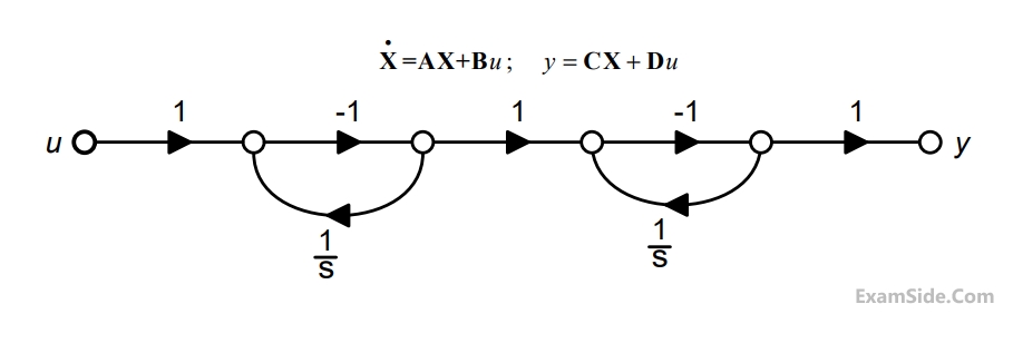
The signal flow graph for a system is given below. The transfer function $$\frac{Y(s)}{U(s)}$$ for this system is

12
Which one of the following statements is NOT TRUE for a continuous time causal
and stable LTI system?
13
A polynomial $$f\left(x\right)\;=\;a_4x^4\;+\;a_3x^3\;+\;a_2x^2\;+\;a_1x\;-\;a_0$$ with all coefficients positive has
14
The Bode plot of a transfer function G (s) is shown in the figure below.

The gain (20 log $$\left| {G(s)} \right|$$ ) is 32 dB and -8dB at 1rad/s and 10rad/s respectively. The phase is negative for all $$\omega .$$ Then G(s) is
15
The state diagram of a system is shown below. A system is shown below. A system is described by the state variable equations
The state transition matrix eAt of the system shown in the figure above is
16
The state diagram of a system is shown below. A system is shown below. A system is described by the state variable equations
The state-variable equations of the system shown in the figure above are
17
In the circuit shown below, Q
1 has negligible collector-to-emitter saturation voltage and the diode
drops negligible voltage across it under forward bias. If V
CC is +5 V, X and Y are digital signals
with 0 V as logic 0 and V
CC as logic 1, then the Boolean expression for Z is

18
In the sum of products function f (x,y,z) = $$\sum {} $$m (2,3,4,5), the prime implicants are
19
A bulb in a staircase has two switches, one switch being at the ground floor and the other one at the
first floor. The bulb can be turned ON and also can be turned OFF by any one of the switches
irrespective of the state of the other switch. The logic of switching of the bulb resembles.
20
The return loss of a device is found to be 20 dB. The voltage standing wave ratio (VSWR) and magnitude of reflection coefficient are respectively.
21
A monochromatic plane wave of wavelength $$\lambda = 600$$ is propagating in the direction as shown in the
figure below. $${\overrightarrow E _i},\,{\overrightarrow E _r}$$ and $${\overrightarrow E _t}$$ denote incident, reflected, and transmitted electric field vectors associated with the wave.
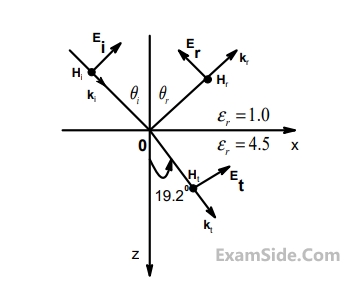
The angle of incidence $${\theta _i}$$ and the expression for $${\overrightarrow E _i}$$ are
22
A monochromatic plane wave of wavelength $$\lambda = 600$$ is propagating in the direction as shown in the
figure below. $${\overrightarrow E _i},\,{\overrightarrow E _r}$$ and $${\overrightarrow E _t}$$ denote incident, reflected, and transmitted electric field vectors associated with the wave.
The expression for $${\overrightarrow E _r}$$ is
23
The divergence of the vector field $$\overrightarrow A\;=\;x{\widehat a}_x\;+\;y{\widehat a}_y\;+\;z{\widehat a}_z$$ is
24
In a forward biased P-N junction diode, the sequence of events that best describes
the mechanism of current flow is
25
In the circuit shown below, the knee current of the ideal Zener diode is 10 mA. To
maintain 5V across R
L, the minimum value of R
L
in Ω and the minimum power
rating of the Zener diode in mW, respectively, are

26
In IC technology, dry oxidation (using dry oxygen) as compared to wet oxidation
(using steam or water vapor) produces
27
In a MOSFET operating in the saturation region, the channel length modulation
effect causes
28
The small-signal resistance (i.e., $${{d{V_B}} \over {d{I_D}}}$$ ) in $$k\Omega $$ offered by the n-channel MOSFET M shown in the figure below, at bias point of V
B = 2V is (device data for M: device transconductance parameter
kN = $${\mu _n}{C_{ox}^{'}}$$ (W/L)= 40$$\mu {\rm A}/{V^2},$$ threshold voltage VTN=1V, and neglect body effect and channel length modulation effects)

29
The minimum eigenvalue of the following matrix is $$\left[ {\matrix{
3 & 5 & 2 \cr
5 & {12} & 7 \cr
2 & 7 & 5 \cr
} } \right]$$
30
Let $$A$$ be an $$m\,\, \times \,\,n$$ matrix and $$B$$ an $$n\,\, \times \,\,m$$ matrix. It is given that determinant $$\left( {{{\rm I}_m} + AB} \right) = $$determinant $$\left( {{{\rm I}_n} + BA} \right),$$ where $${{{\rm I}_k}}$$ is the $$k \times k$$ identity matrix. Using the above property, the determinant of the matrix given below is $$\left[ {\matrix{
2 & 1 & 1 & 1 \cr
1 & 2 & 1 & 1 \cr
1 & 1 & 2 & 1 \cr
1 & 1 & 1 & 2 \cr
} } \right]$$
31
Consider a vector field $$\overrightarrow A \left( {\overrightarrow r } \right).$$ The closed loop line integral $$\oint {\overrightarrow A \bullet \overrightarrow {dl} } $$ can be expressed as
32
The divergence of the vector field $$\,\overrightarrow A = x\widehat a{}_x + y\widehat a{}_y + z\widehat a{}_z\,\,$$ is
33
Let $$U$$ and $$V$$ be two independent zero mean Gaussian random variables of variances $${1 \over 4}$$ and $${1 \over 9}$$ respectively. The probability $$\,P\left( {3V \ge 2U} \right)\,\,$$ is
34
Consider two identically distributed zero - mean random variables $$U$$ and $$V.$$ Let the cumulative distribution functions of $$U$$ and $$2V$$ be $$F(x)$$ and $$G(x)$$ respectively. Then for all values of $$x$$
35
For 8085 microprocessor, the following program is executed.

At the end of program, accumulator contains
36
There are four chips each of 1024 bytes connected to a 16 bit address bus as
shown in the figure below. RAMs 1,2,3 and 4 respectively are mapped to
addresses

37
Two magnetically uncoupled inductive coils have Q factors q1 and q2 at the
chosen operating frequency. Their respective resistances are R1 and R2. When
connected in series, their effective Q factor at the same operating frequency is
38
Three capacitors C1 ,C2 and C3 whose values are 10 µF, 5µF and 2µF respectively, have breakdown voltages of 10V, 5V, and 2V respectively. For the
interconnection shown below, the maximum safe voltage in Volts that can be
applied across the combination, and the corresponding total charge in µC stored
in the effective capacitance across the terminals are respectively.

39
Consider the following figure

The current IS in Amps in the voltage source, and voltage VS in Volts across the
current source respectively, are
40
Consider the following figure
The current in the 1Ω resistor in Amps is
41
A source vs(t) = V cos 100 $$\pi$$t has an internal impedance of (4 + j3) $$\Omega$$. If a purely resistive load connected to this source has to extract the maximum power out of the source, its value in $$\Omega$$ shoud be
42
In the circuit shown below, if the source voltage V
s =100$$\angle$$53.13
0V then the
Thevenin’s equivalent voltage in Volts as seen by the load resistance R
L is

43
The following arrangement consists of an ideal transformer and an attenuator
which attenuates by a factor of 0.8. An ac voltage V
wx1 = 100V is applied across
WX to get an open circuit voltage YZ1 V across YZ. Next, an ac voltage
V
YZ2 =100V is applied across YZ to get an open circuit voltage V
WX2 across WX.
Then, V
YZ1 / V
WX1 , V
WX2 / V
YZ2 are respectively,

44
Consider a delta connection of resistors and its equivalent star connection as
shown below. If all elements of the delta connection are scaled by a factor k, k > 0,
the elements of the corresponding star equivalent will be scaled by a factor of

45
A system is described by the differential equation $$${{{d^2}y} \over {d{t^2}}} + 5{{dy} \over {dt}} + 6y\left( t \right) = x\left( t \right)$$$
Let x(t) be a rectangular pulse given by
$$$x\left( t \right) = \left\{ {\matrix{
{1\,\,\,\,\,\,\,\,\,0 \le \,t\, \le 2} \cr
{0\,\,\,\,\,otherwise} \cr
} } \right.$$$
Assuming that y(0) = 0 $${{dy} \over {dt}} = 0$$ at t = 0, the Laplace transform of y(t) is
46
The DFT of a vector [a b c d] is the vector [α β γ δ ]. Consider the product

The DFT of the vector [ p q r s] is a scaled version of
47
The impulse response of a system is h(t) = t u(t). For an input u(t - 1), the output is
48
Two system with impulse responses h1(t) and h2(t) are connected in cascade. Then the overall impulse response of the cascaded system is given by
49
The impulse response of a continuous time system is given by $$h(t) = \delta (t - 1) + \delta (t - 3)$$. The value of the step response at t = 2 is
50
A band-limited signal with a maximum frequency of 5 kHz is to be sampled. According to the sampling theorem, the sampling frequency which is not valid is
51
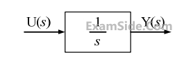
Assuming zero initial condition, the response y (t) of the system given below to a unit step input u(t) is
52
Let g(t) = $${e^{ - \pi {t^2}}}$$, and h(t) is a filter matched to g(t). If g(t) is applied as input to h(t), then the Fourier transform of the output is
53
For a periodic signal v(t) = 30 sin 100t + 10cos 300t + 6sin $${\rm{(500t + }}\,\pi /4)$$, the fundamental frequency in rad/s is