$${r_d} = 20K\Omega ,\,\,{I_{DSS}}\, = \,10mA,\,\,{V_P} = - 8V$$

ID and VDS under DC conditions are respectively


$${r_d} = 20K\Omega ,\,\,{I_{DSS}}\, = \,10mA,\,\,{V_P} = - 8V$$
Transconductance in milli-Siemens (mS) and voltage gain of the amplifier are respectively.
$${r_d} = 20K\Omega ,\,\,{I_{DSS}}\, = \,10mA,\,\,{V_P} = - 8V$$
Zi and Zo of the circuit are respectively


If the input probability density function is divided into three regions as shown in figure, the value of 'a' in the figure is
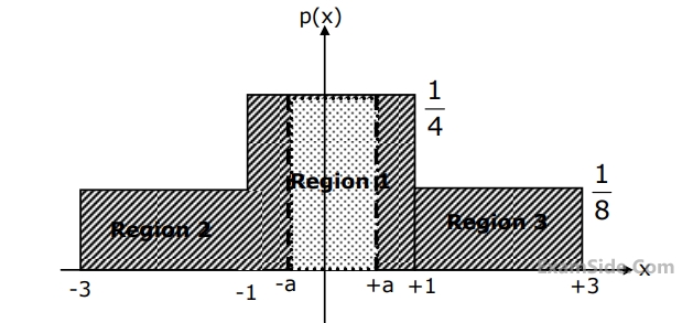
The quantization noise power for the quantization region between –a and +a in the figure is


| A | B | C | D |
|---|---|---|---|
| 0 | 0 | 0 | 0 |
| 0 | 0 | 1 | 0 |
| 0 | 1 | 0 | 0 |
| 0 | 1 | 1 | 1 |
| 1 | 0 | 0 | 0 |
| 1 | 0 | 1 | 0 |
| 1 | 1 | 0 | 1 |
| 1 | 1 | 1 | 0 |

 The reflection coefficient is given by
The value of the load resistance is
The reflection coefficient is given by
The value of the load resistance is $$\overline H \left( {x,y,z,t} \right) = 10\,\sin \left( {50000t + 0.004x + 30} \right){\mathop a\limits^ \cap _y}$$
Where $${\mathop a\limits^ \cap _y}$$ denotes the unit vector in $$y$$ direction. The wave is propagating with a phase velocity

Group $$-$$ $${\rm I}$$
$$E.$$ Newton $$-$$ Raphson method
$$F.$$ Runge-Kutta method
$$G.$$ Simpson's Rule
$$H.$$ Gauss elimination
Group $$-$$ $${\rm II}$$
$$(1)$$ Solving non-linear equations
$$(2)$$ Solving linear simultaneous equations
$$(3)$$ Solving ordinary differential equations
$$(4)$$ Numerical integration method
$$(5)$$ Interpolation
$$(6)$$ Calculation of eigen values
Consider an 8085 microprocessor system
If in addition following code exists from 0109H onwards ORI 40H, ADD M What will be the result in the accumulator after the last instruction is executed
Consider an 8085 microprocessor system
The following program starts at locaton 0100H.
LXI SP, 00FF
LXI H, 0107
MVI A, 20H
SUB M
The contents of accumulator wnen the program counter reaches 0109H is


If R1 = R2 = R4 = R and R3 = 1.1R in the bridge circuit shown in figure, then the reading in the ideal voltmeter connected between a and b is

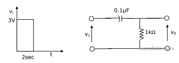
A square pulse of 3 volts amplitude is applied to C-R circuit shown in figure. The capacitor is initially uncharged. The output voltage v0 at time t=2 sec is
For the circuit shown in figure, Thevenin’s voltage and Thevenin’s equivalent resistance at terminals a – b is


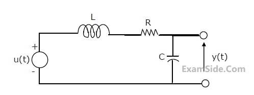
Impedance Z as shown in the figure is:

GROUP 1
E- continuous and aperiodic signal
F- continuous and periodic signal
G- discrete and aperiodic signal
H- discrete and periodic signal
Group 2
1- Fourier representation is continuous and aperiodic
2- Fourier representation is discrete and aperiodic
3- Fourier representation is continuous and periodic
4- Fourier representation is discrete and periodic


The Fourier transform of y(2n) will be

The sequence $$$y(n)=\left\{\begin{array}{l}x\left(\frac n2-1\right)\;\;\;for\;n\;even\\0\;\;\;\;\;\;\;\;\;\;\;\;\;\;\;\;for\;n\;odd\end{array}\right.$$$
will be