1
Assume that the OP_AMP in the figure, ideal

(a) Obtain an expression for V0 in terms of Vs, R, and the reverse saturation current Is of the transiostor.
(b) If R = 1$$\Omega $$, Is = 1pA and the thermal voltage VT = 25mV, then what is the value of the output voltage V0 for an input voltage Vs = 1V?
(c) Suppose that the transistor in the feedback path is replaced by a p-n junction diode with a reverse saturation current of Is. The p-side of the diode is connected to node A and the n-side to node B. Then what is the expression for V0 in terms Vs, R and Is ?
2
The current gain of a BJT is
3
An emitter-follower amplifier is shown in the figure, Z
i is the impedance looking into the base of the transistor and Z
0 is the impedance looking into the emitter of the transistor

(a)Draw the small signal equivalent circuit of the amplifier.
(b)Obtain an expression for zi.
(c)Obtain an expression for z0.
4
An npn BJT has gm = 38 mA/V, $${C_\mu }\, = {10^{ - 14}}$$ F, $${C_\pi }\, = 4\, \times {10^{ - 13}}\,F$$ and DC current gain $$\beta \, = \,90$$. For this transistor fT and $${f_\beta }$$ are
5
The Oscillator circuit shown in the figure is

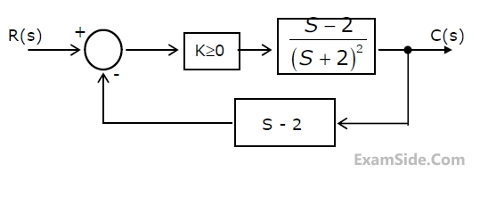
6
The ideal Op-Amp has the following characteristics.
7
Consider the following two statements.
Statement 1: Astable Multivibrator can be used for generating Square Wave.
Statement 2: Bistable Multivibrator can be used for storing binary information.
8
The Inverting Op-Amp shown in the figure, has an Open-loop gain of 100. The closed loop gain $${{{V_o}} \over {{V_s}}}$$ is

9
In the figure assume the Op-Amps to be ideal. The output V
0 of the circuit is

10
An Amplifier using an Op-Amp with a Slew-Rate SR = V/$$\mu $$sec, has a gain of 40 dB. If this amplifier has to faith fully amplify sinsoidal signals from dc to 20 KHz. Without introducing any Slew Rate induced distortion, then the input signal level must not exceed.
11
The PDF of a Gaussian random variable X is given by $${p_x}(x) = \,{1 \over {3\sqrt {2\pi } }}\,\exp \,[ - \,{(x - 4)^2}/18]$$.
The probability of the event {X = 4} is
12
A band limited signal is sampled at the Nyquist rate. The signal can be recovered by passing the samples through
13
During transmission over a communication channel, bit errors occur independently with probability 'p'. If a block of n bits is transmitted, the probability of at most one bit error is equal to
14
A video transmission system transmits 625 picture frames per second. Each frame consists of a $$400\,\, \times \,\,400$$ pixel grid with 64 intensity levels per pixel. The data rate of the system is
15
The root-locus diagram for a closed loop feedback system is shown in Figure. The system is overdamped.

16
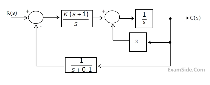
A feedback control system is shown in figure

(a) Draw the signal-flow graph that represents the system.
(b) Find the total number of loops in the graph and determine the loop-gains of
all the loops.
(c) Find the number of all possible combination of non-touching loops taken two
at a time.
(d) Determine the transfer function of the system using the signal-flow graph.
17
If the characteristic equation of a closed-loop system is s2 + 2s + 2 =0, then the
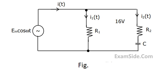
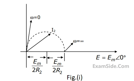
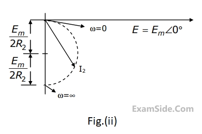
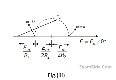
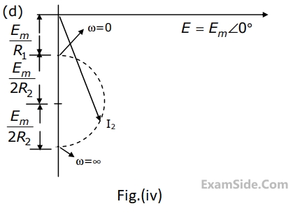
system is
18
The equivalent of the block diagram in Figure is given as

19
An electrical system and its signal-flow graph representations are shown in Figure
(a) and (b) respectively. The values of G
2 and H, respectively are

20
The feedback control system in Figure is stable
21
Consider the feedback control system shown in figure.
(a) Find the transfer function of the system and its characteristic equation.
(b) Use the Routh-Hurwitz criterion to determine the range of 'K' for which the
system is stable.
22
Given the $$G\left(s\right)H\left(s\right)=\frac K{s\left(s+1\right)\left(s+3\right)}$$, the point of intersection of the asymptotes
of the root loci with the real axis is
23
The Nyquist plot for the open-loop transfer function G(s) of a unity negative
feedback system is shown in figure. if G(s) has no pole in the right half of s-plane,
the number of roots of the system characteristic equation in the right half
of s-plane is

24
The open-loop DC gain of a unity negative feedback system with closed-loop
transfer function $${{s + 4} \over {{s^2} + 7s + 13}}$$ is
25
For the feedback control system shown in the figure, the process transfer function is
G
p(s) = $${1 \over {s(s + 1)}},$$ and the amplification factor of the Power amplifier is K$$ \ge $$0.
The design specifications required for the system, time constant is 1 sec and a damping ratio of 0.707.

(a) Find the desired location of the closed loop poles.
(b) Write down the requiredcharacteristic equation for the system. Hense determine the PD controller transfer function G
p(s) when K = 1.
(c) Sketch the root-locus for the system.
27
For the digital block shown in Figure. 2(a), the output Y=f(S
3,S
2,S
1,S
0) where S
3
is MSB and S
0 is LSB. Y is given in terms of minterms as $$Y\, = \,\sum m\left( {1,5,6,7,11,12,13,15} \right)$$ and its complements $$\overline Y \, = \,\sum m\left( {0,2,3,4,8,9,10,14} \right)$$.


(a) Enter the logical values in the given Karnaugh map [figure2(b)] for the output
Y.
(b) Write down the expression for Y in sum-of products from using minimum
number of terms.
(c) Draw the circuit for the digital logic boxes using four 2-input NAND gates
only for each of the boxes.
28
The digital block in the figure is realized using two positive edge triggered D flip-flops. Assume that for t < t
0, Q
1 = Q
2 =0. The circuit in the digital block is given by

29
The 2’s complement representation of –17 is
30
For the ring oscillator shown in the figure, the propagation delay of each inverter is 100 pico sec. What is the fundamental frequency of the oscillator output?

31
In the TTL circuit in Figure 2.11, $${S_0}$$ to $${S_0}$$ are select lines and $${X_7}$$ and $${X_0}$$are input lines. $${S_0}$$ and $${X_0}$$ are LSB'.
The output Y is

32
A transmission line is distortionless if
33
If a plane electromagnetic wave satisfies the equation $${{{\partial ^2}\,{E_x}} \over {\partial \,{z^2}}} = \,{c^2}{{{\partial ^2}\,{E_x}} \over {\partial \,{t^2}}},$$ the wave propagates in the
34
A uniform plane electromagnetic wave incident normally on a plane surface of a dielectric material is reflected with a VSWR of 3. What is the percentage of incident power that is reflected?
35
The phase velocity of waves propagating in a hollow metal waveguide is
36
The dominant mode in a rectangular waveguide is $$T{E_{10}}$$, because this mode has
37
A medium has breakdown strength of $$16$$ KV/m r.m.s. Its relative permeability is $$1.0$$ and relative permittivity is $$4.0$$. A plane electromagnetic wave is transmitted through the medium. Calculate the maximum possible power flow density and the associated magnetic filed.
38
In a uniform linear array, four isotropic radiating elements are spaced $$\lambda /4$$ apart. The progressive phase shift between the elements required for forming the main beam at 60° off the end-fire is
39
A medium wave radio transmitter operating at a wavelength of 492 m has a tower antenna of height 124m. What is the radiation resistance of the antenna?
40
A rectangular hollow metal waveguide has dimensions a = 2.29 cm and b = 1.02 cm. Microwave power at 10 GHz is transmitted through the waveguide in the $$T{E_{10}}$$ mode.
(a) Calculate the cut-off wavelength and the guide wavelength for this mode.
(b) What are the other (TE or TM) modes that can propagate through the waveguide?
(c) If a = b = 2.29 cm, what are the modes which can propagate through the waveguide?
41
A material has conductivity of 10-2 mho/m and a relative permittivity of 4. The
frequency at which the conduction current in the medium is equal to the
displacement current is
43
Solve the differential equation $${{{d^2}y} \over {d{x^2}}} + y = x\,\,$$ with the following conditions $$(i)$$ at $$x=0, y=1$$ $$(ii)$$ at $$x=0, $$ $${y^1} = 1$$
44
An 8085 microprocessor based system uses a 4K × 8-bit RAM whose starting
address is AA00H. The address of the last byte in this RAM is
45
The circuit shown in Fig. is operating in steady-state with switch $${S_1}$$ closed. The switch $${S_1}$$ is opened at $$t\, = \,0$$.
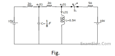
(a) Find $${i_L}\left( {{0^ + }} \right)$$.
(b) Find $${e_1}\left( {{0^ + }} \right)$$.
(c) Using nodal equations and Laplace transform approach, find an expression
for the voltage across the capacitor for all $$t\, = \,0$$.
46
47
If each branch of a Delta circuit has impedance $$\sqrt 3 \,Z$$, then each branch of the equivalent Wye circuit has impedance
48
The Z parameters $${Z_{11}}$$ and $${Z_{21}}$$ for the 2-port network in Fig. are

49
The admittance parameters of a 2-port network shown in Fig. are given by $${Y_{11}} = \,2\,\,mho$$, $${Y_{12}}$$ = - 0.5 mho, $${Y_{21}}$$ = 4.8 mho, $${Y_{22}}$$ = 1 mho. The output port is terminated with a load admittance $${Y_L}$$ = 0.2 mho. Find $${E_2}$$ for each of the following conditions:
(a) $${E_1} = \,10\,\angle \,{0^{ \circ \,}}\,V$$
(b) $${I_1} = \,10\,\angle \,{0^{ \circ \,}}\,A$$
(c) A source $$10\,\angle \,{0^{ \circ \,}}\,V$$ in series with a 0.25 $$\Omega $$ resistor is connected to the input port.

50
The voltage e0 in figure is

51
In figure, the value of the load resistor R which maximizes the power
delivered to it is

52
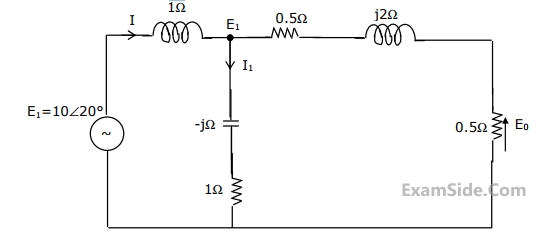
For the circuit shown in the figure, determine the phasors E
2, E
0, I and I
1.
53
The admittance parameter Y
12 in the 2-port network in Figure is

54
The voltage e0 in Fig. is

55
If a signal f(t) has energy E, the energy of the signal f(2t) is equal to
56
The region of convergence of the z- transform of a unit step function is
57
The transfer function of a system is given by $$H\left( s \right) = {1 \over {{s^2}\left( {s - 2} \right)}}$$. The impulse response of the system is
58
The impulse response function of four linear system S1, S2, S3, S4 are given respectively by
$${h_1}$$(t), = 1;
$${h_2}$$(t), = U(t);
$${h_3}(t)\, = \,{{U(t)} \over {t + 1}}$$;
$${h_4}(t)\, = {e^{ - 3t}}U(t)$$ ,
where U (t) is the unit step function. Which of these system is time invariant, causal, and stable?
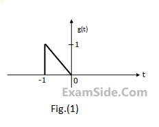
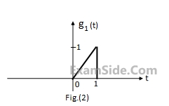
59
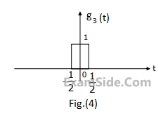
The Fourier transform $$G(\omega )$$ of the signal g(t) in Fig.(1) is given as
$$G(\omega ) = {1 \over {{\omega ^2}}}({e^{j\omega }} - j\omega {e^{j\omega }} - 1)$$.
Using this information, and the time-shifting and time-scaling properties, determine and Fourier transform of signals in Fig (2), (3) and (4).
60
A band limited signal is sampled at the Nyquist rate. The signal can be recovered by passing the samples through
61
A base band signal g(t) band limited to 100 Hz modulates a carrier of frequency $${{f_0}}$$ Hz. The modulated signal g(t) $$\cos 2\,\pi \,{f_0}t$$ is transmitted over a channel whose input x and output y are related by $$y = 2x + {x^2}$$. The spectrum of g(t) is shown in Fig. Sketch the spectrum of the transmitted signal and the spectrum of the received signal.

62
The Nyquist sampling interval, for the signal Sinc(700t) + Sinc(500t) is
63
Let $$\delta (t)$$ denote the delta function. The value of the the integral $$\int\limits_{ - \infty }^\infty {\delta (t)} \,\,\cos \left( {{{3\,\,t} \over 2}} \right)dt$$ is
64
The PSD and the power of a signal g(t) are, respectively, Sg($$\omega$$) and Pg. The PSD
and the power of the signal ag(t) are, respectively