1
Find the output voltage, V
0 in the following circuit assuming that the Op-Amps are ideal.

2
The bandwidth of an n-stage tuned amplifier, with each stage having a band
width of B, is given by
3
For the amplifier circuit of figure, the transistor has a $$\mathrm\beta$$ of 800. The mid-band voltage
gain $$V_0/V_1$$ of the circuit will be

4
In a multi-stage RC-Coupled Amplifier the coupling capacitor.
5
Negative feedback in Amplifiers.
6
In a transistor push-pull Amplifier
7
For the ideal Op-Amp circuit of fig. Determine the output voltage V
0

8
Which of the following demodulator(s) can be used for demodulating the signal
$$x(t)\;=\;5\left(1+2\;\cos200\mathrm{πt}\right)\cos\;20000\;\mathrm{πt}$$ .
9
A superheterodyne radio receiver with an intermediate frequency of 455 KHz is
tuned to a station operating at 1200 KHz. The associated image frequency is
______ KHz.
10
If $$s^3+\;3s^2\;+\;4s\;+A\;=\;0$$ ,then all the roots of this equation are in the left half plane
provided that
11
The truth table for the output Y in terms of three inputs A, B and C are given in
table. Draw a logic circuit realization using only NOR gates.

12
Signals A,B,C,D and $$\overline D $$ are available. Using a single 8 - to - 1 multiplexer and no other gate, implement the Boolean function.
$$f(A,B,C,D) = B.C + A.B.\bar D + \bar A.\bar C.\bar D$$
13
A pulse train with a frequency of 1 MHz is counted using a modulo-1024 ripple-counter built with J-K flip flops. For proper operation of the counter, the maximum permissible propagation delay per flip flop stage is ______ n sec.
14
2’s complement representation of a 16-bit number (one sign bit and 15
magnitude bits) is FFFI. Its magnitude in decimal representation is
15
Boolean expression for the output of XNOR (equivalence) logic gate with inputs A and B is
16
For the logic circuit shown in Figure, the output is equal to

17
A material is described by the following electrical parameters at a frequency of $$10$$ GHz is $$\sigma = {10^6}$$ mho/m, $$\mu = {\mu _0},$$ and $$ \in /{ \in _0} = 10.$$ The material at this frequency is considered to be $$\left( {{ \in _0} = {1 \over {36\,\,\pi }} \times {{10}^{ - 9}}\,\,F/m} \right)$$
18
Consider a transmission line of characteristic impedance 50 ohm. Let it be terminated at one end by ( + j50) ohm. The VSWR produced by it in the transmission line will be
19
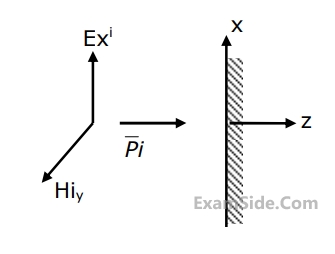
A plane wave is incident normally on a perfect conductor as shown in Fig. Here $$E_x^i,\,\,H_y^i$$ and $$\overrightarrow P {}^i$$ are electric field, magnetic field and Poynting vector respectively, for the incident wave. The reflected wave should have
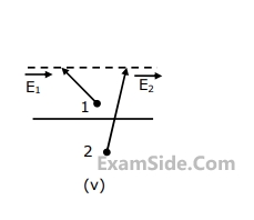
20
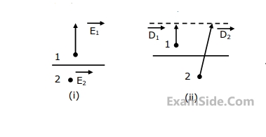
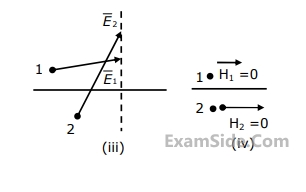
Match the following descriptions with each of the diagrams given in Fig. Fields are near the interface, but on opposite sides of the boundary. Vectors are drawn to scale.
(a) Medium $$1$$ and medium $$2$$ are dielectrics with $${\varepsilon _1} > {\varepsilon _2}$$
(b) Medium $$1$$ and medium $$2$$ are dielectrics with $${\varepsilon _1} < {\varepsilon _2}$$
(c) Medium $$2$$ is a perfect conductor
(d) Impossible
(e) Medium $$1$$ is a perfect conduct
21
Consider an array of two non-directional radiators with spacing $$d\,\, = \,\,0.5\,\,\lambda $$. Determine the directions of maximum radiation when the radiators are excited as shown in Fig.. Calculate the phase shift required for turning the direction of the maximum radiation by $${90^ \circ }$$ keeping the separation d unchanged.

22
An optical fiber consists of a cylindrical dielectric rod of refractive index $$n_1$$, surrounded by another dielectric of refractive index $$n_2$$ where $$n_2$$ < $$n_1$$ as shown in the following Fig. If a ray is incident from air at angle i to the axis, then it undergoes total internal reflection at the interface AB if

23
Given,$$\overrightarrow V=x\cos^2y\;\;\widehat{\mathrm i}\;+\;\mathrm x^2\mathrm e^\mathrm z\;\widehat{\mathrm j}\;+\;\mathrm{zsin}^2\mathrm y\;\widehat{\mathrm k}$$ and S the surface of a unit cube with one
corner at the origin and edges parallel to the coordinate axes, the value of the
integral is

24
The built-in potential (Diffusion Potential) in a p-n junction
25
If the linear velocity $${\overrightarrow V }$$ is given by $$\overrightarrow V = {x^2}y\overrightarrow i + xyz\overrightarrow j - y{z^2}\overrightarrow k $$ then the angular velocity $$\overrightarrow W $$ at the point $$\left( {1,1, - 1} \right)$$ is _______.
26
Given the differential equation $${y^1} = x - y$$ with initial condition $$y(0)=0.$$ The value of $$y(0.1)$$ calculated numerically upto the third place of decimal by the $${2^{nd}}$$ order Runge-Kutta method with step size $$h=0.1$$ is
27
In a microprocessor, the register which holds the address of the next instruction to be fetched is
28
In a microcomputer, wait states are used to
29
An infinite grid is built up by connecting resistors in the manner indicated in
figure, where each branch represents one ohm resistor. Calculate the effective
resistance between the nodes A and B.

30
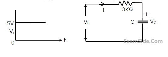
In the following circuit the capacitance varies as C = KQ, where K is a constant
equal to 0.5 Farads/Coulomb and Q, the charge on the capacitor in Coulombs.
Determine the current through the circuit and sketch the voltage waveform
across the capacitor (V
C) for a step input V
i as shown in figure.
32
A network contains linear resistors and ideal voltage sources. If values of all the
resistors are doubled, then the voltage across each resistor is
33
The two electrical sub-network N1 and N2 are connected through three resistors
as shown in figure. The voltage across 5 Ω resistor and 1 Ω resistor are
given to be 10 V and 5 V, respectively. Then voltage across 15 Ω resistor is

34
If the secondary winding of the ideal transformer shown in the circuit of the
figure has 40 turns, the number of turns in the primary winding for maximum
power transfer to the 2 Ω resistor will be

35
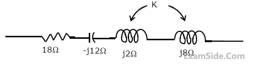
In the series circuit shown in figure, for series resonance, the value of the
coupling coefficient K will be
36
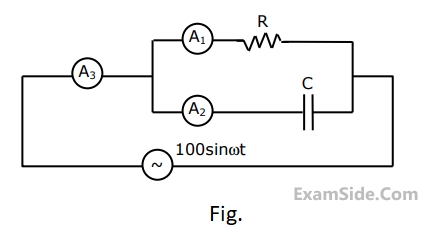
In the circuit of figure, when switch S1
is closed, the ideal ammeter M
1
reads 5A.
What will be ideal voltmeter M
2
read when S
1
is kept open? (The value of E is not
specified).

37
A dc circuit shown in figure has a voltage source V, a current source I and several
resistors. A particular resistor R dissipates a power of 4 Watts when V alone is
active. The same resistor R dissipates a power of 9 Watts when I alone is active.
The power dissipated by R when both sources are active will be

38
If $$F\left( s \right) = L\left[ {f\left( t \right)} \right] = {K \over {\left( {s + 1} \right)\,\left( {{s^2} + 4} \right)}}$$ then $$\matrix{
{Lim\,f\,\left( t \right)} \cr
{t \to \infty } \cr
} $$ is given by
39
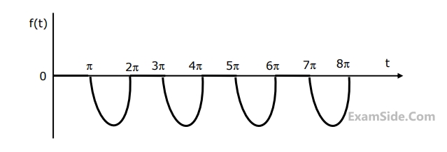
The Laplace transform of the periodioc function f(t) describe4d by the curve below, i.e.,
$$f\left( t \right) = \left\{ {\matrix{
{\sin \,t\,\,\,if\,\left( {2n - 1} \right)\pi \le t \le 2n\pi } \cr
{0\,\,\,\,\,\,\,\,otherwise} \cr
} } \right.$$
is _________. (fill in the blank), n is an integer.
40
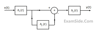
Consider the following interconnection of the three LTI systems (Fig.1). $${h_1}(t)$$ , $${h_2}(t)$$ and $${h_3}(t)$$ are the impulse responses of these three LTI systems with $${H_1}(\omega )$$, $${H_2}(\omega )$$, and $${H_3}(\omega )$$ as their respective Fourier transforms. Given that $${h_1}\,(t)\, = \,{d \over {dt}}\left[ {{{\sin ({\omega _0}t)} \over {2\,\pi \,t}}} \right],{H_2}(\omega ) = \exp \left( {{{ - j2\pi \omega } \over {{\omega _0}}}} \right)$$
$${h_3}\,(t)\, = u(t)\,and\,x(t)\, = \,\sin \,2\,{\omega _0}t\, + \,\cos \,({\omega _0}t/2),$$ find the output y(t).
41
Sketch the waveform (with properly marked axes) at the output of a matched filter matched for a signal s(t), of duration T, given by $$s(t) = \left\{ {\matrix{
{A\,\,\,\,for} & {0 \le t < {2 \over 3}T} \cr
{0\,\,\,\,\,\,for} & {{2 \over 3}T \le t < T} \cr
} } \right.$$
42
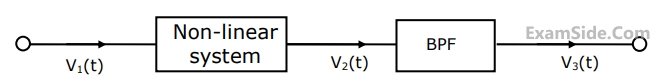
Obtain an expression for the signal in figure, for the signal $${v_3}(t)$$ in Fig for $${v_1}(t) = 100\cos (2000\pi t) + 4\sin (200\pi t)$$. Assume that $${v_2}(t)$$=$${v_1}(t)$$+0.1 $$v_1^2(t)$$ and that the BPF is an ideal unity gain filter with pass band from 800 Hz to 1200 Hz.
43
A low pass signal m(t) band-limited to B Hz is sampled by a periodic rectangular pulse train, $${p_\tau }(t)$$ of period $${T_s}$$ = 1/(3B) sec. Assuming natural sampling and that the pulse amplitude and pulse width are A volts and 1/(30B) sec, respectively, obtain an expression for the frequency spectrum of the sampled signal $${m_s}$$(t)