A particle of charge ' $q$ ' and mass ' $m$ ' moves in a circular orbit of radius ' $r$ ' with angular speed ' $\omega$ '. The ratio of the magnitude of its magnetic moment to that of its angular momentum depends on
A charged particle moving with a velocity $$\vec{v}=v_1 \hat{i}+v_2 \hat{j}$$ in a magnetic field $$\vec{B}$$ experiences a force $$\vec{F}=F_1 \hat{i}+F_2 \hat{j}$$. Here $$v_1, v_2, F_1, F_2$$ all are constants. Then $$\overrightarrow{\mathrm{B}}$$ can be
A wire carrying a steady current I is kept in the x-y plane along the curve $$y=A \sin \left(\frac{2 \pi}{\lambda} x\right)$$. A magnetic field B exists in the z-direction. The magnitude of the magnetic force in the portion of the wire between x = 0 and x = $$\lambda$$ is

A bar magnet falls from rest under gravity through the centre of a horizontal ring of conducting wire as shown in figure. Which of the following graph best represents the speed (v) vs. time (t) graph of the bar magnet?

Two infinite line-charges parallel to each other are moving with a constant velocity v in the same direction as shown in the figure. The separation between two line-charges is d. The magnetic attraction balances the electric repulsion when, [ c = speed of light in free space ]
An electron revolves around the nucleus in a circular path with angular momentum $$\overrightarrow L $$. A uniform magnetic field $$\overrightarrow B $$ is applied perpendicular to the plane of its orbit. If the electron experiences a torque $$\overrightarrow T $$, then
A straight wire is placed in a magnetic field that varies with distance x from origin as $$\overrightarrow B = {B_0}\left( {2 - {x \over a}} \right)\widehat k$$. Ends of wire are at (a, 0) and (2a, 0) and it carries a current I. If force on wire is $$\overrightarrow F = I{B_0}\left( {{{ka} \over 2}} \right)\widehat j$$, then value of k is
A horizontal semi-circular wire of radius r is connected to a battery through two similar springs X and Y to an electric cell, which sends current I through it. A vertically downward uniform magnetic field B is applied on the wire, as shown in the figure. What is the force acting on each spring?

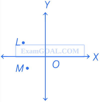
Consider two infinitely long wires parallel to Z-axis carrying same current I in the positive z-direction. One wire passes through the point L at coordinates ($$-$$1, +1) and the other wire passes through the point M at coordinates ($$-$$1, $$-$$1). The resultant magnetic field at the origin O will be
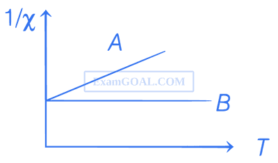
For two types of magnetic materials A and B, variation of $$1\over\chi$$ ($$\chi$$ : susceptibility) versus temperature T is shown in the figure. Then,

As shown in the figure, a single conducting wire is bent to form a loop in the form of a circle of radius r concentrically inside a square of side a, where a : r = 8 : $$\pi $$. A battery B drives a current through the wire. If the battery B and the gap G are of negligible sizes, determine the strength of magnetic field at the common centre O.

As shown in the figure, a wire is bent to form a D-shaped closed loop, carrying current I, where the curved part is a semi-circle of radius R. The loop is placed in a uniform magnetic field B, which is directed into the plane of the paper. The magnetic force felt by the closed loop is

"The loop will .........".


As shown in figure, a rectangular loop of length 'a' and width 'b' and made of a conducting material of uniform cross-section is kept in a horizontal plane where a uniform magnetic field of intensity B is acting vertically downward. Resistance per unit length of the loop is $$\lambda$$ $$\Omega$$/m. If the loop is pulled with uniform velocity 'v' in horizontal direction, which of the following statement is/are true?
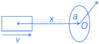
A small bar magnet of dipole moment M is moving with speed v along x-direction towards a small closed circular conducting loop of radius a with its centre O at x = 0 (see figure). Assume x >> a and the coil has a resistance R. Then, which of the following statements is/are true?