1
A clipper Circuit is shown below

Assuming forward voltage drops of the diodes to be $$0.7V,$$ the input-output transfer characteristics of the circuit is
2
The transistor used in the circuit shown below has a $$\beta $$ of $$30$$ and $${{\rm I}_{CBO}}$$ is negligible.

If the forward voltage drop of diode is $$0.7V.$$ Then the current through collector will be
3
A low pass filter with a cut-off frequency of $$30Hz$$ is cascaded with a high pass filter with a cut off frequency of 20Hz. The resultant system of filters coil function as
4
For the circuit shown below, the correct transfer characteristics is

5
An open loop system represented by the transfer function $$G\left( s \right) = {{\left( {s - 1} \right)} \over {\left( {s + 2} \right)\left( {s + 3} \right)}}$$ is
6
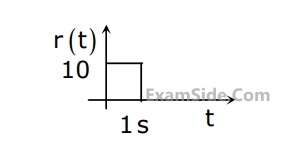
The steady state error of a unity feedback linear system for a unit step input is $$0.1.$$ The steady state error of the same system, for a pulse input $$r(t)$$ having a magnitude of $$10$$ and a duration of one second, as shown in the figure is
7
A two-loop position control system is shown below.
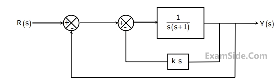
The gain $$k$$ of the Tacho-generator influences mainly the
8
The response $$h(t)$$ of a linear time invariant system to an impulse $$\delta \left( t \right),$$ under initially relaxed condition is $$h\left( t \right) = \,{e^{ - t}} + {e^{ - 2t}}.$$ The response of this system for a unit step input $$u(t)$$ is
9
The open loop transfer function $$G(s)$$ of a unity feedback control system is given as, $$G\left( s \right) = {{k\left( {s + {2 \over 3}} \right)} \over {{s^2}\left( {s + 2} \right)}}.\,\,$$ From the root locus, it can be inferred that when $$k$$ tends to positive infinity
10
The frequency response of a linear system $$G\left( {j\omega } \right)$$ is provided in the tubular form below.
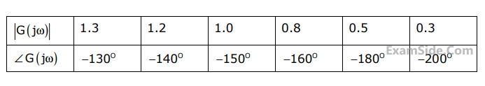
The gain margin and phase margin of the system are
11
The output $$Y$$ of the logic circuit given below is

12
A two-bit counter circuit is shown below

It the state $${Q_A}{Q_B}$$ of the counter at the clock time $${t_n}$$ is $$'10'$$ then the state $${Q_A}{Q_B}$$ of the counter at $${t_n} + 3$$ (after three clock cycles) will be
13
A portion of the main program to call a subroutine $$SUB$$ in an $$8085$$ environment is given below:
$$\eqalign{
& LXI\,\,\,\,\,\,\,\,\,\,\,\,\,D\,\,\,DISP \cr
& LP\,\,\,\,\,\,\,\,\,\,\,\,\,\,\,CALL\,\,\,SUB \cr} $$
It is desired that control be returned to $$LP+DISP+3$$ when the $$RET$$ instruction is executed in the subroutine. The set of instructions that precede the $$RET$$ instruction in the subroutine are
14
The r.m.s value of the current i(t) in the circuit shown below is

15
The voltage applied to a circuit is $$100\sqrt2\cos\left(100\mathrm{πt}\right)$$ volts and the circuit draws
a current of $$10\sqrt2\;\sin\left(100\mathrm{πt}+\mathrm\pi/4\right)$$ amperes. Taking the voltage as the
reference phasor, the phasor representation of the current in amperes is
16
An RLC circuit with relevant data is given below.

The power dissipated in the resistor R is
17
An RLC circuit with relevant data is given below.
The current $${\underline I}_C$$ in the figure above is
18
In the circuit given below, the value of R required for the transfer of maximum
power to the load having a resistance of 3 Ω is

19
The bridge circuit shown in the fig below is used for the measurement of an unknown element Z
x. The bridge circuit is best suited when Z
x is a

20
Consider the following statement:
(i) The compensating coil of a low power factor wattmeter compensates the effect of the impedance of the current coil.
(ii) The compensating coil of a low power factor wattmeter compensates the effect of the impedance of the voltage coil circuit.
21
A dual trace oscilloscope is set to operate in the ALTernate. The control input of the multiplexer used in the y-circuit is fed with a signal having a frequency equal to
22
A $$4\,{1 \over 2}$$ digit $$DMM$$ has the error specification as $$0.2$$% of reading $$+10$$ counts. If a dc voltage of $$100$$ $$v$$ is read on its $$200$$ $$V$$ full scale. The maximum error that can be expressed in the reading is _______.
23
The direct axis and quadrature axis reactances of a salient pole alternator are $$1.2$$ $$p.u$$ and $$1.0$$ $$p.u$$ respectively. The armature resistance is negligible. If this alternator is delivering rated $$kVA$$ at $$upf$$ and at rated voltage then its power angle is
24
A three-phase 440V, 6 pole, 50Hz, squirrel cage induction motor is running at a
slip of 5%. The speed of stator magnetic field to rotor magnetic field and speed
of rotor with respect to stator magnetic field are
25
A 4–point starter is used to start and control the speed of a
26
A 220 V, DC shunt motor is operating at a speed of 1440 rpm. The armature
resistance is 1.0 $$\Omega$$ and armature current is 10 A. of the excitation of the machine
is reduced by 10%, the extra resistance to be put in the armature circuit to
maintain the same speed and torque will be
27
A single phase air core transformer, fed from a rated sinusoidal supply, is
operating at no load. The steady state magnetizing current drawn by the
transformer from the supply will have the waveform
28
A three-phase, salient pole synchronous motor is connected to an infinite bus. It
is operated at no load a normal excitation. The field excitation of the motor is
first reduced to zero and then increased in reverse direction gradually. Then the
armature current
29
A capacitor is made with a polymeric dielectric having an $$\varepsilon_0$$ of 2.26 and a
dielectric breakdown strength of 50 kV/cm. The permittivity of free space is
8.85 pF/m. If the rectangular plates of the capacitor have a width of 20 cm and a
length of 40 cm, then the maximum electric charge in the capacitor is
30
Given $$f(t)$$ and $$g(t)$$ as shown below

$$g(t)$$ can be expressed as
31
Given $$f(t)$$ and $$g(t)$$ as shown below
The laplace transform of $$g(t)$$ is
32
A point $$z$$ has been plotted in the complex plane as shown in the figure below
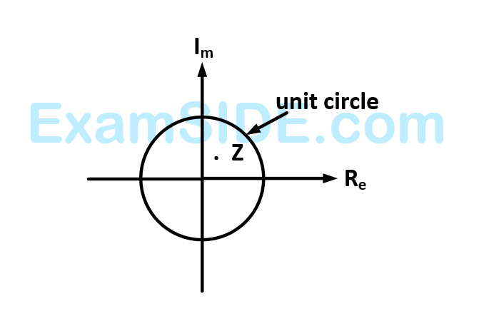
The plot of the complex number $$w = 1/z$$
33
The two vectors $$\left[ {\matrix{
1 & 1 & 1 \cr
} } \right]$$ and $$\left[ {\matrix{
1 & a & {{a^2}} \cr
} } \right]$$ where $$a = - {1 \over 2} + j{{\sqrt 3 } \over 2}$$ and $$j = \sqrt { - 1} $$ are
34
The matrix $$\left[ A \right] = \left[ {\matrix{
2 & 1 \cr
4 & { - 1} \cr
} } \right]$$ is decomposed into a product of lower triangular matrix $$\left[ L \right]$$ and an upper triangular $$\left[ U \right].$$ The properly decomposed $$\left[ L \right]$$ and $$\left[ U \right]$$ matrices respectively are
35
Roots of the algebraic equation $${x^3} + {x^2} + x + 1 = 0$$ are
36
The function $$f\left( x \right) = 2x - {x^2} + 3\,\,$$ has
37
The two vectors $$\left[ {\matrix{
{1,} & {1,} & {1} \cr
} } \right]$$ and $$\left[ {\matrix{
{1,} & {a,} & {{a^2}} \cr
} } \right]$$ where $$a = {{ - 1} \over 2} + j{{\sqrt 3 } \over 2}$$ are
38
With $$K$$ as constant, the possible solution for the first order differential equation $${{dy} \over {dx}} = {e^{ - 3x}}$$ is
39
Solution, the variable $${x_1}$$ and $${x_2}$$ for the following equations is to be obtained by employing the Newton $$-$$ Raphson iteration method
equation (i) $$10\,{x_2}\,\sin \,{x_1} - 0.8 = 0$$
$$\,\,\,\,\,\,\,\,\,\,\,\,\,\,$$ $$10\,x_2^2\, - 10\,{x_2}\cos \,{x_1} - 0.6 = 0$$
Assuming the initial values $${x_1} = 0.0$$ and $${x_2} = 1.0$$ the Jacobian matrix is
40
Circuit turn-off time of an $$SCR$$ is defined as the time
41
The input voltage given to a converter is
$${V_i} = 100\sqrt 2 \,\,\,\sin \,\,\,\left( {100\pi t} \right)\,\,V$$
The current drawn by the converter is
$${i_i} = 10\sqrt 2 \,\,\,\sin \,\,\,\left( {100\pi t - {\pi \over 3}} \right)\,\, + 5\sqrt 2 $$
$$\sin \left( {300\pi t + {\pi \over 4}} \right)\,\, + \,\,2\sqrt 2 \,\,\sin \left( {500\pi t - {\pi \over 6}} \right)A$$
The input power factor of the converter is
42
The input voltage given to a converter is
$${V_i} = 100\sqrt 2 \,\,\,\sin \,\,\,\left( {100\pi t} \right)\,\,V$$
The current drawn by the converter is
$${i_i} = 10\sqrt 2 \,\,\,\sin \,\,\,\left( {100\pi t - {\pi \over 3}} \right)\,\, + 5\sqrt 2 $$
$$\sin \left( {300\pi t + {\pi \over 4}} \right)\,\, + \,\,2\sqrt 2 \,\,\sin \left( {500\pi t - {\pi \over 6}} \right)A$$
The active power drawn by the converter is
43
A solar energy installation utilize a three – phase bridge converter to feed energy into power system through a transformer of $$400V/400 V,$$ as shown below. The energy is collected in a bank of $$400$$ $$V$$ battery and is connected to converter through a large filter choke of resistance $$10\Omega $$.

The $$kVA$$ rating of the input transformer is
44
A solar energy installation utilize a three – phase bridge converter to feed energy into power system through a transformer of $$400V/400 V,$$ as shown below. The energy is collected in a bank of $$400$$ $$V$$ battery and is connected to converter through a large filter choke of resistance $$10\Omega $$.

The maximum current through the battery will be
45
A voltage commutated chopper circuit, operated at $$500Hz,$$ is shown below. If the maximum value of load current is $$10A,$$ then the maximum current through the main $$(M)$$ and auxiliary $$(A)$$ thyristors will be

46
A three-phase current source inverter used for the speed control of an induction motor is to be realized using MOSFET switches as shown below. Switches $${S_1}$$ to $${S_6}$$ are identical switches.

The proper configuration for realizing switches $${S_1}$$ to $${S_6}$$ is
47
Two generator units $$G1$$ and $$G2$$ are connected by $$15$$ $$kV$$ line with a bus at the mid-point as shown below

$${G_1} = 250\,\,MVA.\,\,\,15kV,\,\,$$ positive sequence $$X = 25$$% on its own base
$${G_2} = 100\,\,MVA.\,\,\,15kV,\,$$ positive sequence $$X = 10$$% on its own base
$${L_1}$$ and $${L_2}$$ $$= 10$$ $$km,$$ positive sequence $$ X = 0.225$$ $$\,\,\Omega /km$$
For the above system, the positive sequence diagram with the p.u values on the $$100$$ $$MVA$$ common
48
Two generator units $$G1$$ and $$G2$$ are connected by $$15$$ $$kV$$ line with a bus at the mid-point as shown below
$${G_1} = 250\,\,MVA.\,\,\,15kV,\,\,$$ positive sequence $$X = 25$$% on its own base
$${G_2} = 100\,\,MVA.\,\,\,15kV,\,$$ positive sequence $$X = 10$$% on its own base
$${L_1}$$ and $${L_2}$$ $$= 10$$ $$km,$$ positive sequence $$ X = 0.225$$ $$\,\,\Omega /km$$
In the above system the three-phase fault $$MVA$$ at the bus $$3$$ is
49
A nuclear power station of $$500$$ $$MW$$ capacity is located at $$300$$ km away from a load center. Select the most suitable power evacuation transmission configuration among the following options.
50
For enhancing the power transmission in along $$EHV$$ transmission line, the most preferred is to connect a
51
A lossy capacitor $${C_x}$$, rated for operation at $$5$$ $$kV,$$ $$50$$ $$Hz$$ is represented by an equivalent circuit with an ideal capacitor $${C_p}$$ in parallel with a resistor $${R_p}$$. The value $${C_p}$$ is found to be $$0.102$$ $$\mu F$$ and the value of $${R_p}$$ $$=$$ $$1.25$$ $$M\Omega .$$ Then the power loss and $$tan\delta $$ of the lossy capacitor operating at the rated voltage, respectively, are
52
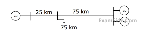
A load center of 120 MW derives power from two power stations connected by 220 kV transmission lines of 25 km and 75 km as shown in the figure below. The three generators G1,G2 and G3 are of 100 MW capacity each and have identical fuel cost characteristics. The minimum loss generation schedule for supplying the 120 MW load is
53
A negative sequence relay is commonly used to protect
54
A three–bus network is shown in the figure below indicating the p.u. impedances of each element
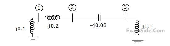
The bus admittance matrix, $$Y$$-$$bus,$$ of the network is
55
A point Z has been plotted in the complex plane, as shown in figure below.
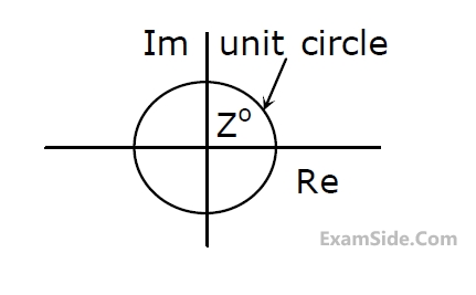
The plot of the complex number $$y=\frac1z$$ is
56
Given two continuous time signals $$x\left(t\right)=e^{-t}$$ and $$y\left(t\right)=e^{-2t}$$ which exist for t > 0,
the convolution z(t) = x(t)*y(t) is
57
A low–pass filter with a cut-off frequency of 30 Hz is cascaded with a high-pass
filter with a cut-off frequency of 20 Hz. The resultant system of filters will function
as
58
The response h(t) of a linear time invariant system to an impulse $$\delta\left(t\right)$$, under
initially relaxed condition is $$h\left(t\right)=e^{-t}\;+\;e^{-2t}$$. The response of this system for a
unit step input u(t) is
59
The fourier series expansion $$$f\left(t\right)\;=\;a_0\;+\;\sum_{n=1}^\infty a_n\cos\;n\omega t\;+\;b_n\sin\;n\omega t$$$ of the periodic
signal shown below will contain the following nonzero terms

60
Let the Laplace transform of a function f(t) which exists for t > 0 be F1(s) and
the Laplace transform of its delayed version f(1 - $$\tau$$) be F2(s). Let F1*(s) be the
complex conjugate of F1(s) with the Laplace variable set as $$s=\sigma\;+\;j\omega$$. If G(s) =$$\frac{F_2\left(s\right).F_1^\ast\left(s\right)}{\left|F_1\left(s\right)\right|^2}$$
, then the inverse Laplace transform of G(s) is