


Its root locus plot against $$K$$ is
$$F\left( s \right) = {s^5} - 3{s^4} + 5{s^3} - 7{s^2} + 4s + 20$$
$$F\left( s \right) = 0$$ has

How many times $$DCR$$ $$L$$ instruction will be executed?
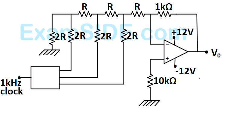
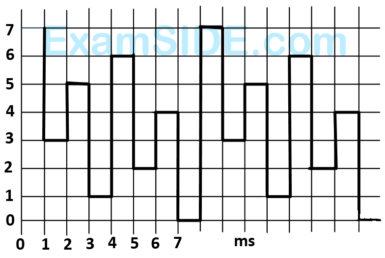
The output achieved is different as shown in figure. What could be the possible cause of this error?
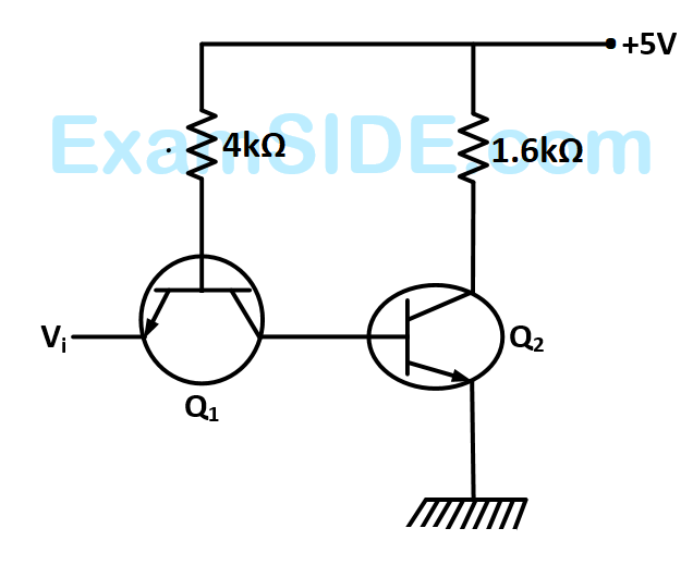
$${R_i} = 1\,\,M\,\Omega ,\,\,{R_0} = 10\,\Omega ,\,\,A = {10^6}\,\,V/V.$$ If $${V_i} = 1\,\,\mu V,\,\,$$ the output voltage, input impedance and output impedance respectively are


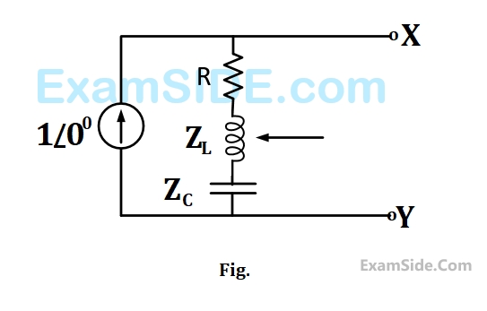
The phasor diagram which is applicable to this circuit is


No Load Test: $$400V$$ $$6A$$ $$1002W$$
Blocked Rotor Test: $$90V$$ $$15A$$ $$762W$$
Neglecting copper loss in No Load Test and core loss in Blocked Rotor Test, estimate motor's full load efficiency.
The line to line induced $$emf$$, for a three phase star connection is approximately
The line to line induced $$emf,$$ for two phase connection is
The starting torque when the motor is started direct-on-line is (use approximate equivalent circuit model)
What is the maximum efficiency (in %) at unity $$pf$$ load?
The iron loss $$\left( {{P_i}} \right)$$ in $$kW,$$ under full load operation are
1. This is a point from the continuity equation
2. Divergence of current density is equal to the decrease of charge per unit volume per unit time at every point.
3. This is Maxwell's divergence equation
4. This represents the conservation of charge.


The average output voltage of the chopper will be
The minimum time in $$\mu $$ sec for which the $$SCR$$ $$M$$ should be ON is

The pre-fault voltages are $$1.0$$ $$p.u.$$ at all the buses. The system was unloaded prior to the fault. A solid $$3$$ phase fault takes place at bus $$2.$$
The per unit fault feeds from generators connected to buses $$1$$ and $$2$$ respectively are
The pre-fault voltages are $$1.0$$ $$p.u.$$ at all the buses. The system was unloaded prior to the fault. A solid $$3$$ phase fault takes place at bus $$2.$$
The post fault voltages at buses $$1$$ and $$3$$ in per unit respectively are
The initial accelerating power (in pu) will be
If the initial accelerating power is $$X$$ pu, the initial acceleration in elect deg/sec2, and the inertia constant in MJ-sec/elect deg respectively will be
$$A = D = 0.94\,\angle \,10,\,\,\,B = 130\,\angle \,730,\,\,\,C = 0.001\,\angle \,900.\,\,$$ If the sending end voltage of the line for a given load delivered at nominal voltage is $$240$$ $$kV$$, the % voltage regulation of the line is
$$\,\,\,\,\,\,\,\,\,\,\,\,\,\,\,\,\,\,\,\,\,\,\,\,\,\,\,\,\,\,\,\, = 2$$ is the input and
$$y\left[ n \right] = 0;\,n < - 1,\,n > 2,\,y\left[ { - 1} \right] = - 1,\, = y\left[ 1 \right],\,y\left[ 0 \right] = 3,\,y\left[ 2 \right]$$
$$\,\,\,\,\,\,\,\,\,\,\,\,\,\,\,\,\,\,\,\,\,\,\,\,\,\,\,\,\,\,\,\, =- 2$$ is the output of a discrete-time $$LTI$$ system. The system impulse response $$h\left[ n \right]$$ will be
$$\omega = 2\pi \left( {2k} \right)/T;\,\,k = 1,2,........$$ Also, no sine terms are present. Then $$x(t)$$ satisfies the equation