Control Systems
1
GATE EE 2017 Set 2
MCQ (Single Correct Answer)
+1
-0.3
When a unit ramp input is applied to the unity feedback system having closed loop transfer function $${{C\left( s \right)} \over {R\left( s \right)}} = {{Ks + b} \over {{s^2} + as + b}},\,\left( {a > 0,\,b > 0,\,K > 0} \right),$$ the steady state error will be
2
GATE EE 2014 Set 2
Numerical
+1
-0
The closed-loop transfer function of a system is $$T\left( s \right) = {4 \over {\left( {{s^2} + 0.4s + 4} \right)}}.$$ The steady state error due to unit step input is ________
Your input ____
3
GATE EE 2011
MCQ (Single Correct Answer)
+1
-0.3
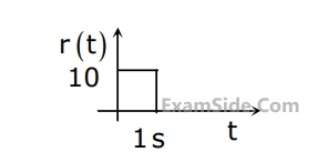
The steady state error of a unity feedback linear system for a unit step input is $$0.1.$$ The steady state error of the same system, for a pulse input $$r(t)$$ having a magnitude of $$10$$ and a duration of one second, as shown in the figure is
4
GATE EE 2010
MCQ (Single Correct Answer)
+1
-0.3
For the system $${2 \over {\left( {s + 1} \right)}},$$ the approximate time taken for a step response to reach $$98$$% of its final value is
GATE EE Subjects
Electromagnetic Fields
Signals and Systems
Engineering Mathematics
General Aptitude
Power Electronics
Power System Analysis
Analog Electronics
Control Systems
Digital Electronics
Electrical Machines
Electric Circuits
Electrical and Electronics Measurement