Control Systems
1
GATE EE 2009
MCQ (Single Correct Answer)
+2
-0.6
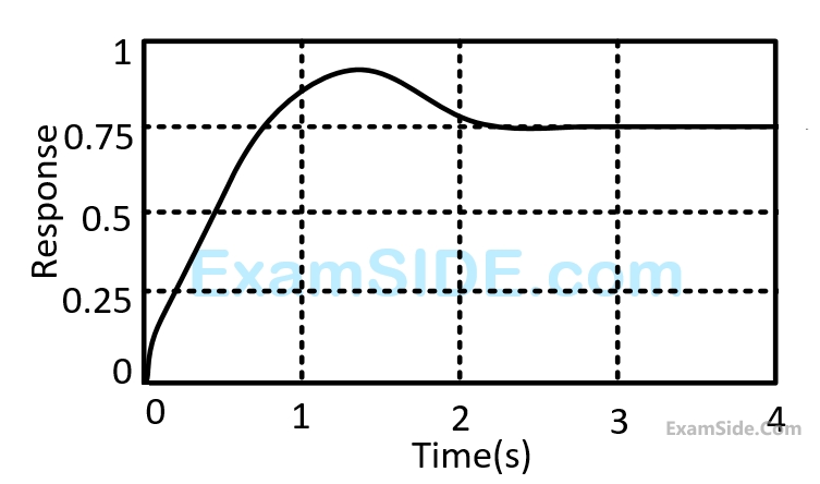
The unit - step response of a unity feedback system with open loop transfer function $$G\left( s \right) = {K \over {\left( {s + 1} \right)\left( {s + 2} \right)}}$$ is shown in the figure. The value of $$K$$ is
2
GATE EE 2008
MCQ (Single Correct Answer)
+2
-0.6
The transfer function of a linear time invariant system is given as $$G\left( s \right) = {1 \over {{s^2} + 3s + 2}}$$
The steady state value of the output of the system for a unit impulse input applied at time instant $$t=1$$ will be
3
GATE EE 2008
MCQ (Single Correct Answer)
+2
-0.6
The transfer function of a system is given as $${{100} \over {{s^2} + 20s + 100}}.$$ The system is
4
GATE EE 2007
MCQ (Single Correct Answer)
+2
-0.6
$$R-L-C$$ circuit shown in figure

For a step input $${e_{i,}}$$ the overshoot in the output $${e_{0,}}$$ will be
GATE EE Subjects
Electromagnetic Fields
Signals and Systems
Engineering Mathematics
General Aptitude
Power Electronics
Power System Analysis
Analog Electronics
Control Systems
Digital Electronics
Electrical Machines
Electric Circuits
Electrical and Electronics Measurement