Control Systems
Signal Flow Graph and Block Diagram
Marks 1Marks 2Marks 5
Basic of Control Systems
Marks 1Marks 2
Frequency Response Analysis
Marks 1Marks 2Marks 5Marks 8Marks 10
Root Locus Diagram
Marks 1Marks 2
State Space Analysis
Marks 1Marks 2Marks 5Marks 10
1
GATE ECE 2010
MCQ (Single Correct Answer)
+1
-0.3
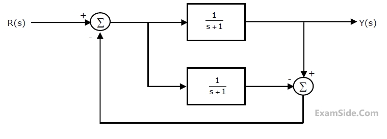
The transfer function Y(s)/R(s) of the system shown is GATE ECE 2010 Control Systems - Signal Flow Graph and Block Diagram Question 20 English
A
$$0$$
B
$$\frac1{s+1}$$
C
$$\frac1{s+2}$$
D
$$\frac2{s+3}$$
2
GATE ECE 2001
MCQ (Single Correct Answer)
+1
-0.3
The equivalent of the block diagram in Figure is given as GATE ECE 2001 Control Systems - Signal Flow Graph and Block Diagram Question 14 English
A
GATE ECE 2001 Control Systems - Signal Flow Graph and Block Diagram Question 14 English Option 1
B
GATE ECE 2001 Control Systems - Signal Flow Graph and Block Diagram Question 14 English Option 2
C
GATE ECE 2001 Control Systems - Signal Flow Graph and Block Diagram Question 14 English Option 3
D
GATE ECE 2001 Control Systems - Signal Flow Graph and Block Diagram Question 14 English Option 4
3
GATE ECE 1995
MCQ (Single Correct Answer)
+1
-0.3
Signal flow graph is used to find
A
stability of the system
B
controllability of the system
C
transfer function of the system
D
poles of the system
GATE ECE Subjects
Signals and Systems
Network Theory
Control Systems
Digital Circuits
General Aptitude
Electronic Devices and VLSI
Analog Circuits
Engineering Mathematics
Microprocessors
Communications
Electromagnetics