Digital Circuits
1
GATE ECE 2011
MCQ (Single Correct Answer)
+1
-0.3
The output Y in the circuit below is always ‘1’ when 
2
GATE ECE 2010
MCQ (Single Correct Answer)
+1
-0.3
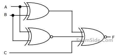
For the output F to be 1 in the logic circuit shown, the input combination should be
3
GATE ECE 2010
MCQ (Single Correct Answer)
+1
-0.3
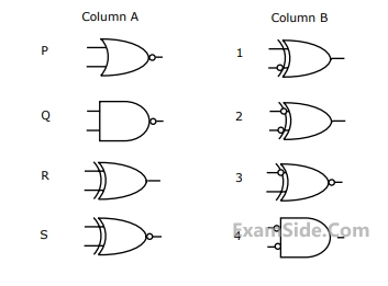
Match the logic gates in column A with their equivalents in column B.
4
GATE ECE 2002
MCQ (Single Correct Answer)
+1
-0.3
If the input to the digital circuit (in the figure) consisting of a cascade of 20 XOR-gates is X then the output Y is equal to

Questions Asked from Marks 1
GATE ECE 2025 (1) GATE ECE 2023 (1) GATE ECE 2016 Set 1 (1) GATE ECE 2016 Set 3 (1) GATE ECE 2015 Set 2 (1) GATE ECE 2015 Set 3 (1) GATE ECE 2014 Set 4 (1) GATE ECE 2013 (1) GATE ECE 2011 (1) GATE ECE 2010 (2) GATE ECE 2002 (1) GATE ECE 2001 (1) GATE ECE 2000 (1) GATE ECE 1997 (1) GATE ECE 1995 (1) GATE ECE 1994 (1) GATE ECE 1993 (2) GATE ECE 1989 (1) GATE ECE 1988 (5)
GATE ECE Subjects
Signals and Systems
Network Theory
Control Systems
Digital Circuits
General Aptitude
Electronic Devices and VLSI
Analog Circuits
Engineering Mathematics
Microprocessors
Communications
Electromagnetics