Digital Circuits
1
GATE ECE 2014 Set 1
MCQ (Single Correct Answer)
+2
-0.6
The output F in the digital logic circuit shown in the figure is

2
GATE ECE 2008
MCQ (Single Correct Answer)
+2
-0.6
Which of the follwing Boolean expression correctly represents the relation between P, Q, R and M1?

3
GATE ECE 2002
MCQ (Single Correct Answer)
+2
-0.6
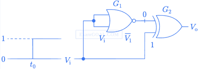
The gates G1 and G2 in figure have propagation delays of 10nsec and 20nsec respectively. If the input Vi makes an abrupt change from logic 0 to 1 at
time t = t0, then the output waveform V0 is
A

B

C

D

4
GATE ECE 2001
MCQ (Single Correct Answer)
+2
-0.6
In the figure the LED

GATE ECE Subjects
Signals and Systems
Network Theory
Control Systems
Digital Circuits
General Aptitude
Electronic Devices and VLSI
Analog Circuits
Engineering Mathematics
Microprocessors
Communications
Electromagnetics