Digital Circuits
1
GATE ECE 2000
Subjective
+5
-0
The operating conditions (ON = 1, OFF = 0) of three pumps (x,y,z) are to be
monitored. x = 1 implies that pump X is on. It is required that the indicator (LED)
on the panel should glow when a majority of the pumps fail.
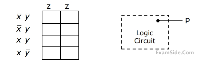
(a) Enter the logical values in the K-map in the format shown in figure 3(a). Derive
the minimal Boolean sum-of-products expression whose output is zero when a majority of the pumps fail.
(b) The above expression is implemented using logic gates, and point P is the
output of this circuit, as shown in figure 3(b). P is at 0 V when a majority of the pumps fails and is at 5 V otherwise. Design a circuit to drive the LED using this output. The current through the LED should be 10 mA and the voltage drop across it is 1V. Assume that P can source or sink 10 mA and a 5 V supply is available.
2
GATE ECE 1993
Subjective
+5
-0
The truth table for the output Y in terms of three inputs A, B and C are given in
table. Draw a logic circuit realization using only NOR gates.

Questions Asked from Marks 5
GATE ECE Subjects
Signals and Systems
Network Theory
Control Systems
Digital Circuits
General Aptitude
Electronic Devices and VLSI
Analog Circuits
Engineering Mathematics
Microprocessors
Communications
Electromagnetics