Digital Circuits
1
GATE ECE 2003
MCQ (Single Correct Answer)
+2
-0.6
The circuit shown in figure is a 4-bit DAC
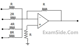 The input bits 0 and 1 are represented by 0 and 5 V respectively. The OP- AMP is ideal, but all the resistances and the 5V inputs have a tolerance of ±10%.
The specification (rounded to the nearest multiple of 5%) for the tolerance of the DAC is
The input bits 0 and 1 are represented by 0 and 5 V respectively. The OP- AMP is ideal, but all the resistances and the 5V inputs have a tolerance of ±10%.
The specification (rounded to the nearest multiple of 5%) for the tolerance of the DAC is
2
GATE ECE 2000
MCQ (Single Correct Answer)
+2
-0.6
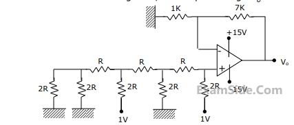
For the 4 bit DAC shown in Figure, the output voltage $${V_0}$$ is
GATE ECE Subjects
Signals and Systems
Network Theory
Control Systems
Digital Circuits
General Aptitude
Electronic Devices and VLSI
Analog Circuits
Engineering Mathematics
Microprocessors
Communications
Electromagnetics