Control Systems
1
GATE EE 2007
MCQ (Single Correct Answer)
+2
-0.6
$$R-L-C$$ circuit shown in figure

If the above step response is to be observed on a non - storage $$CRO,$$ then it would be best have the $${e_i}$$ as a
2
GATE EE 2007
MCQ (Single Correct Answer)
+2
-0.6
Consider the feedback system shown below which is subjected to a unit step input. The system is stable and has following parameters $${k_p} = 4,\,\,{k_i} = 10,\,\,\omega = 500\,\,$$ and $$\xi $$ $$=0.7.$$ The steady state value of $$z$$ is

3
GATE EE 2005
MCQ (Single Correct Answer)
+2
-0.6
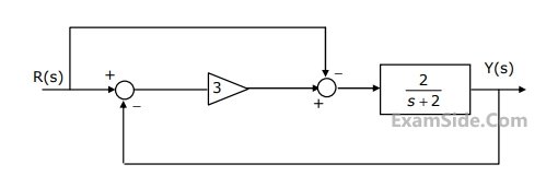
When subjected to a unit step input, the closed loop control system shown in the figure will have a steady state error of

4
GATE EE 2005
MCQ (Single Correct Answer)
+2
-0.6
When subjected to a unit step input, the closed loop control system shown in the figure will have a steady state error of
GATE EE Subjects
Electromagnetic Fields
Signals and Systems
Engineering Mathematics
General Aptitude
Power Electronics
Power System Analysis
Analog Electronics
Control Systems
Digital Electronics
Electrical Machines
Electric Circuits
Electrical and Electronics Measurement