Analog Electronics
Frequency Response
Marks 21
GATE EE 2022
MCQ (Single Correct Answer)
+1
-0.33
For the circuit shown below with ideal diodes, the output will be

2
GATE EE 2017 Set 1
MCQ (Single Correct Answer)
+1
-0.3
For the circuit shown in the figure below, assume that diodes $${D_1},\,{D_2}$$ and $${D_3}$$ are ideal.

The $$DC$$ components of voltages $${v_1}$$ and $${v_2},$$ respectively are
3
GATE EE 2015 Set 2
MCQ (Single Correct Answer)
+1
-0.3
In the following circuit, the input voltage $${V_{in}}$$ is $$100\sin \left( {100\pi t} \right).$$ For $$100\pi RC = 50,$$ the average voltage across $$R$$ (in volts) under steady-state is nearest to

4
GATE EE 2014 Set 2
Numerical
+1
-0
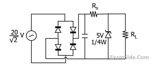
The sinusoidal ac source in the figure has an rms value of $${{20} \over {\sqrt 2 }}\,V.$$ Considering all possible values of $${R_L},\,\,$$ the minimum value of $${R_s}$$ in $$\Omega $$ to avoid burnout of the Zener diode is ______.
Your input ____
Questions Asked from Marks 1
GATE EE Subjects
Electromagnetic Fields
Signals and Systems
Engineering Mathematics
General Aptitude
Power Electronics
Power System Analysis
Analog Electronics
Control Systems
Digital Electronics
Electrical Machines
Electric Circuits
Electrical and Electronics Measurement