Analog Circuits
1
GATE ECE 2014 Set 1
Numerical
+1
-0
In the low - pass filter shown in the figure, for a cut - off frequency of 5 KHz, the value of R2 (in k$$\Omega $$ ) is _________

Your input ____
2
GATE ECE 2013
MCQ (Single Correct Answer)
+1
-0.3
In the circuit shown below, what is the output voltage (vout ) if a silicon transistor Q and an ideal op-amp are used?
3
GATE ECE 2011
MCQ (Single Correct Answer)
+1
-0.3
The circuit below implements a filter between the input current ii and the output voltage v0. Assume that the op-amp- is ideal, The filter implemented is a

4
GATE ECE 2010
MCQ (Single Correct Answer)
+1
-0.3
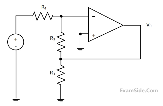
Assuming the OP-AMP to be ideal, the voltage gain of the amplifier shown below is
Questions Asked from Marks 1
GATE ECE 2025 (1) GATE ECE 2022 (1) GATE ECE 2017 Set 1 (1) GATE ECE 2016 Set 1 (2) GATE ECE 2015 Set 2 (2) GATE ECE 2015 Set 3 (1) GATE ECE 2014 Set 4 (1) GATE ECE 2014 Set 2 (1) GATE ECE 2014 Set 1 (1) GATE ECE 2013 (1) GATE ECE 2011 (1) GATE ECE 2010 (2) GATE ECE 2005 (1) GATE ECE 2004 (2) GATE ECE 2003 (1) GATE ECE 2001 (1) GATE ECE 2000 (2) GATE ECE 1999 (1) GATE ECE 1998 (2) GATE ECE 1997 (1) GATE ECE 1996 (1) GATE ECE 1995 (3) GATE ECE 1994 (1)
GATE ECE Subjects
Signals and Systems
Network Theory
Control Systems
Digital Circuits
General Aptitude
Electronic Devices and VLSI
Analog Circuits
Engineering Mathematics
Microprocessors
Communications
Electromagnetics