Digital Circuits
1
GATE ECE 2007
MCQ (Single Correct Answer)
+2
-0.6
In the digital-to-Analog converter circuit shown in the figure below,
$${V_{R\,}}\, = \,10V$$ and $$R\, = \,10k\Omega $$
$${V_{R\,}}\, = \,10V$$ and $$R\, = \,10k\Omega $$
The voltage V0 is
2
GATE ECE 2006
MCQ (Single Correct Answer)
+2
-0.6
A 4-bit D/A converter is connected to a free-running 3-bit UP counter, as shown in the following figure. Which of the following waveforms will be observed at V0=?

In the figure shown above, the ground has been shown by the symbol $$\nabla $$
A

B

C

D

3
GATE ECE 2003
MCQ (Single Correct Answer)
+2
-0.6
The circuit shown in figure is a 4-bit DAC
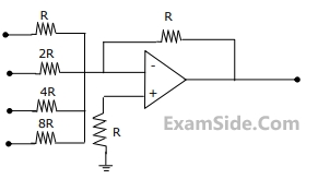 The input bits 0 and 1 are represented by 0 and 5 V respectively. The OP- AMP is ideal, but all the resistances and the 5V inputs have a tolerance of ±10%.
The specification (rounded to the nearest multiple of 5%) for the tolerance of the DAC is
The input bits 0 and 1 are represented by 0 and 5 V respectively. The OP- AMP is ideal, but all the resistances and the 5V inputs have a tolerance of ±10%.
The specification (rounded to the nearest multiple of 5%) for the tolerance of the DAC is
4
GATE ECE 2000
MCQ (Single Correct Answer)
+2
-0.6
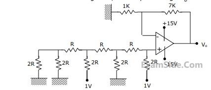
For the 4 bit DAC shown in Figure, the output voltage $${V_0}$$ is
GATE ECE Subjects
Signals and Systems
Network Theory
Control Systems
Digital Circuits
General Aptitude
Electronic Devices and VLSI
Analog Circuits
Engineering Mathematics
Microprocessors
Communications
Electromagnetics