Digital Circuits
1
GATE ECE 2003
MCQ (Single Correct Answer)
+2
-0.6
In the circuit shown in Figure, A is a parallel in, parallel-out 4-bit register, which loads at the rising edge of the clock C. The input lines are connected to a 4-bit bus, W. Its output acts as the input to a 16×4 ROM whose output is floating when
the enable input E is 0. A partial table of the contents of the ROM is as follows

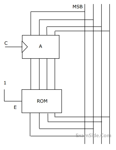
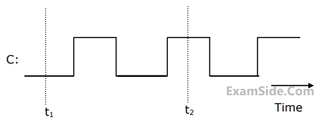
The clock to the register is shown, and the data on the W bus at time t$$_1$$ is 0110. The data on the bus at time t$$_2$$ is
2
GATE ECE 2002
MCQ (Single Correct Answer)
+2
-0.6
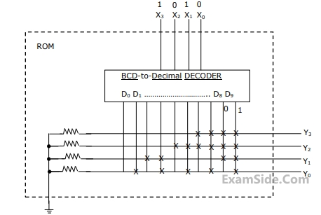
If the input X$$_3$$, X$$_2$$, X$$_1$$, X$$_0$$ to the ROM in figure 2.12 are 8-4-2-1 BCD numbers, then the outpus are Y$$_3$$,Y$$_2$$, Y$$_1$$, Y$$_0$$ are
Questions Asked from Marks 2
GATE ECE Subjects
Signals and Systems
Network Theory
Control Systems
Digital Circuits
General Aptitude
Electronic Devices and VLSI
Analog Circuits
Engineering Mathematics
Microprocessors
Communications
Electromagnetics