Digital Circuits
1
GATE ECE 2015 Set 3
MCQ (Single Correct Answer)
+1
-0.3
In the circuit shown, diodes $${D_1}$$ ,$${D_2}$$ and $${D_3}$$ are ideal, and the inputs $${E_1}$$ , $${E_2}$$ and $${E_3}$$ are “0 V” for
logic ‘0’ and “10 V” for logic ‘1’. What logic gate does the circuit represent?

2
GATE ECE 2014 Set 4
MCQ (Single Correct Answer)
+1
-0.3
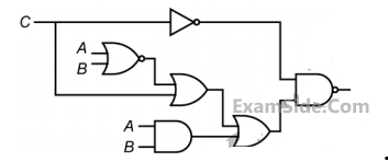
In the circuit shown in the figure, if C = 0, the expression for Y is
3
GATE ECE 2013
MCQ (Single Correct Answer)
+1
-0.3
A bulb in a staircase has two switches, one switch being at the ground floor and the other one at the
first floor. The bulb can be turned ON and also can be turned OFF by any one of the switches
irrespective of the state of the other switch. The logic of switching of the bulb resembles.
4
GATE ECE 2011
MCQ (Single Correct Answer)
+1
-0.3
The output Y in the circuit below is always ‘1’ when 
Questions Asked from Marks 1
GATE ECE 2025 (1) GATE ECE 2023 (1) GATE ECE 2016 Set 3 (1) GATE ECE 2016 Set 1 (1) GATE ECE 2015 Set 2 (1) GATE ECE 2015 Set 3 (1) GATE ECE 2014 Set 4 (1) GATE ECE 2013 (1) GATE ECE 2011 (1) GATE ECE 2010 (2) GATE ECE 2002 (1) GATE ECE 2001 (1) GATE ECE 2000 (1) GATE ECE 1997 (1) GATE ECE 1995 (1) GATE ECE 1994 (1) GATE ECE 1993 (2) GATE ECE 1989 (1) GATE ECE 1988 (5)
GATE ECE Subjects
Signals and Systems
Network Theory
Control Systems
Digital Circuits
General Aptitude
Electronic Devices and VLSI
Analog Circuits
Engineering Mathematics
Microprocessors
Communications
Electromagnetics