Network Theory
State Equations For Networks
Marks 51
GATE ECE 2001
Subjective
+5
-0
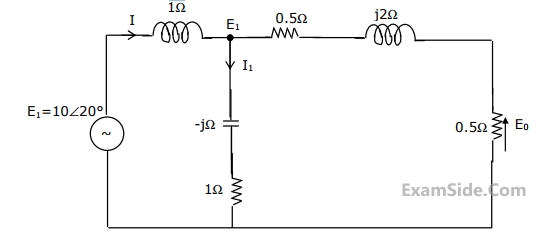
For the circuit shown in the figure, determine the phasors E2, E0, I and I1.
2
GATE ECE 2000
Subjective
+5
-0
For the circuit in Fig. Which is in steady state,
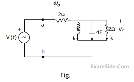
(a)Find the frequency $${\omega _0}$$ at which the magnitude of the impedance across terminals a, b reaches maximum.
(b) Find the impedance across a, b at the frequency $${\omega _0}$$.
(c) If $${v_i}\left( t \right) = V\,\,\sin \left( {{\omega _0}t} \right),$$ find $${i_L}\left( t \right),\,\,{i_c}\left( t \right),{i_R}\left( t \right).$$
3
GATE ECE 1999
Subjective
+5
-0
A coil with a quality factor $$(Q)$$ of $$10$$ is put in series with a capacitor $${C_1}$$ of $$10\,\,\mu F,$$ and the combination is found to draw maximum current when a sinusoidal voltage of frequency $$50$$ $$Hz$$ is applied. A second capacitor $${C_2}$$ is now in parallel with the circuit. What should be the capacitance of $${C_2}$$ for combined circuit to act purely as a resistance for a sinusoidal excitation at a frequency of $$100$$ $$Hz$$? Calculate the rms current drawn by the combined circuit at $$100$$ $$Hz$$ if the applied voltage is $$100V$$ (rms).
4
GATE ECE 1998
Subjective
+5
-0
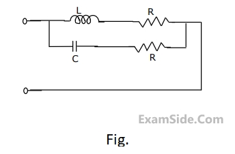
Determine the frequency of resonance and the resonant impedance of the parallel circuit shown in figure. What happens when $$L = C{R^2}$$?
Questions Asked from Marks 5
GATE ECE Subjects
Signals and Systems
Network Theory
Control Systems
Digital Circuits
General Aptitude
Electronic Devices and VLSI
Analog Circuits
Engineering Mathematics
Microprocessors
Communications
Electromagnetics