1
GATE EE 1999
MCQ (Single Correct Answer)
+1
-0.3
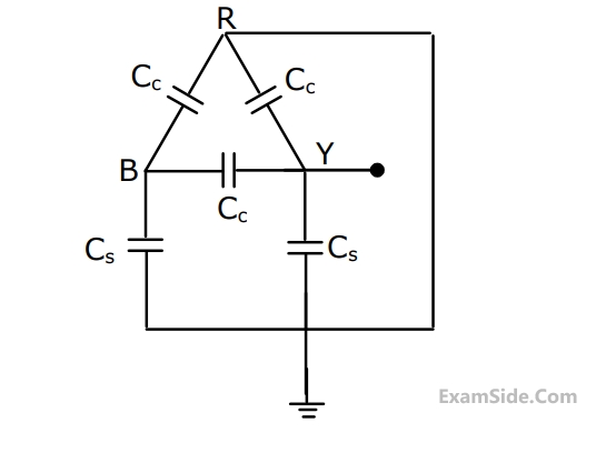
For the circuit shown in Figure, the capacitance measured between terminals $$B$$ and $$Y$$ will be
2
GATE EE 1998
MCQ (Single Correct Answer)
+1
-0.3
In the circuit shown in Figure, it is desired to have a constant direct current $$i(t)$$ through the ideal inductor $$L.$$ The nature of the voltage source $$v(t)$$ must be

3
GATE EE 1997
MCQ (Single Correct Answer)
+1
-0.3
Energy stored in a capacitor over a cycle, when excited by an $$a.c.$$ source is
4
GATE EE 1996
MCQ (Single Correct Answer)
+1
-0.3
The v - i characteristic as seen from the terminal pair (A,B) of the network of Fig.(1) is shown in Fig.(2). If an inductance of value 6 mH is connected across the terminal - pair (A,B), the time constant of the system will be

Questions Asked from Marks 1
GATE EE 2025 (2) GATE EE 2024 (1) GATE EE 2021 (1) GATE EE 2020 (1) GATE EE 2019 (1) GATE EE 2017 Set 1 (2) GATE EE 2016 Set 1 (2) GATE EE 2015 Set 1 (1) GATE EE 2014 Set 2 (1) GATE EE 2014 Set 1 (2) GATE EE 2013 (1) GATE EE 2010 (2) GATE EE 2009 (2) GATE EE 2008 (1) GATE EE 2005 (1) GATE EE 2003 (2) GATE EE 2001 (2) GATE EE 2000 (1) GATE EE 1999 (1) GATE EE 1998 (1) GATE EE 1997 (1) GATE EE 1996 (1) GATE EE 1992 (2)
GATE EE Subjects
Electromagnetic Fields
Signals and Systems
Engineering Mathematics
General Aptitude
Power Electronics
Power System Analysis
Analog Electronics
Control Systems
Digital Electronics
Electrical Machines
Electric Circuits
Electrical and Electronics Measurement