Power System Analysis
High Voltage Dc Transmission
Marks 11
GATE EE 2013
MCQ (Single Correct Answer)
+2
-0.6
For a power system network with $$n$$ nodes, $${Z_{33}}$$ of its bus impedance matrix is $$j0.5$$ per unit. The voltage at mode $$3$$ is $$1.3\angle - {10^0}\,\,$$ per unit. If a capacitor having reactance of $$-j3.5$$ per unit is now added to the network between node $$3$$ and the reference node, the current drawn by the capacitor per unit as
2
GATE EE 2013
MCQ (Single Correct Answer)
+2
-0.6
In the following network, the voltage magnitudes at all buses are equal to $$1$$ p.u., the voltage phase angles are very small, and the line resistance are negligible. All the line reactances are equal to $$j1\Omega .$$
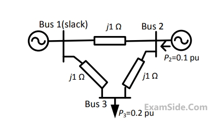
If the base impedance and the line-to-line base voltage are $$100\Omega $$ and $$\,100kV,\,\,$$ respectively, then the real power in MW delivered by the generator connected at the slack bus is
3
GATE EE 2011
MCQ (Single Correct Answer)
+2
-0.6
A three–bus network is shown in the figure below indicating the p.u. impedances of each element
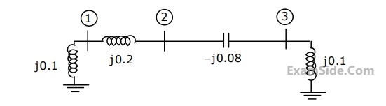
The bus admittance matrix, $$Y$$-$$bus,$$ of the network is
4
GATE EE 2009
MCQ (Single Correct Answer)
+2
-0.6
For the $${Y_{bus}}$$ matrix of a $$4$$-bus system given in per unit, the buses having shunt elements are
$$${Y_{BUS}} = j\left[ {\matrix{
{ - 5} & 2 & {2.5} & 0 \cr
2 & { - 10} & {2.5} & 4 \cr
{2.5} & {2.5} & { - 9} & 4 \cr
0 & 4 & 4 & { - 8} \cr
} } \right]$$$
GATE EE Subjects
Electromagnetic Fields
Signals and Systems
Engineering Mathematics
General Aptitude
Power Electronics
Power System Analysis
Analog Electronics
Control Systems
Digital Electronics
Electrical Machines
Electric Circuits
Electrical and Electronics Measurement