Control Systems
1
GATE ECE 1998
Subjective
+10
-0
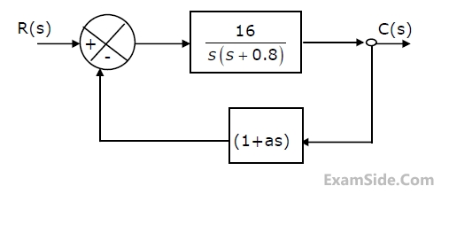
Consider the system shown in Fig. Determine the value of 'a' such that the
damping ratio is 0.5. Also obtain the values of the rise time 'tr' and maximum
overshoot 'Mp' in its step response.
Questions Asked from Marks 10
GATE ECE Subjects
Signals and Systems
Network Theory
Control Systems
Digital Circuits
General Aptitude
Electronic Devices and VLSI
Analog Circuits
Engineering Mathematics
Microprocessors
Communications
Electromagnetics