Consider a distribution feeder, with $R / X$ ratio of 5 . At the receiving end, a 350 kVA load is connected. The maximum voltage drop will occur from the sending end to the receiving end, when the power factor of the load is __________ (round off to three decimal places).
Your input ____
2
GATE EE 2023
Numerical
+1
-0
A 50 Hz, 275 kV line of length 400 km has the following parameters:
Resistance, R = 0.035 $$\Omega$$/km;
Inductance, L = 1 mH/km;
Capacitance, C = 0.01 $$\mu$$F/km;
The line is represented by the nominal-$$\pi$$ model. With the magnitudes of the sending end and the receiving end voltages of the line (denoted by $$V_S$$ and $$V_R$$, respectively) maintained at 275 kV, the phase angle difference ($$\theta$$) between $$V_S$$ and $$V_R$$ required for maximum possible active power to be delivered to the receiving end, in degree is ___________ (Round off to 2 decimal places).
Your input ____
3
GATE EE 2022
MCQ (Single Correct Answer)
+1
-0.33
The geometric mean radius of a conductor, having four equal strands with each strand of radius r, as shown in the figure below, is
A
4r
B
1.414r
C
2r
D
1.723r
4
GATE EE 2018
MCQ (Single Correct Answer)
+1
-0.33
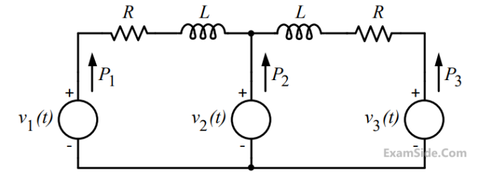
In the figure, the voltages are
$${v_1}\left( t \right) = 100\cos \left( {\omega t} \right)$$
$${v_2}\left( t \right) = 100\cos \left( {\omega t + {\pi \over {18}}} \right)$$
and $${v_3}\left( t \right) = 100\cos \left( {\omega t + {\pi \over {36}}} \right)$$.
The circuit is in sinusoidal steady state, and R << $${\omega L}$$.
P1, P2 and P3 are the average power outputs. Which one of the following statements is true?