Digital Circuits
1
GATE ECE 2016 Set 2
Numerical
+1
-0
Assume that all the digital gates in the circuit shown in the figure are ideal, the resistor 𝑅 = 10 𝑘Ω and the supply voltage is 5 𝑉. The D flip-flops D1, D2, D3, D4 and D5 are initialized with logic
values 0, 1, 0,1 and 0, respectively. The clock has a 30% duty cycle.
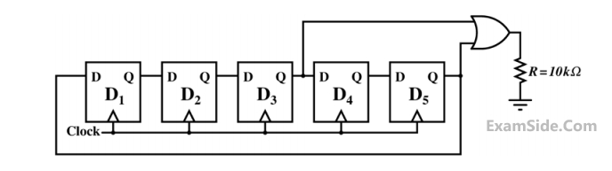
The average power dissipated (in mW) in resistor R is ______.
Your input ____
2
GATE ECE 2015 Set 2
Numerical
+1
-0
A mod-n counter using a synchronous binary up-counter with synchronous clear input is shown in the figure. The value of n is _______.

Your input ____
3
GATE ECE 2015 Set 3
MCQ (Single Correct Answer)
+1
-0.3
The circuit shown consists of J-K flip-flops, each with an active low asynchronous reset ($$\overline {{R_d}} $$ input).
The counter corresponding to this circuit is

4
GATE ECE 2014 Set 1
Numerical
+1
-0
Five JK flip - flops are cascaded to form circuit shown in figure. Clock pulses at a frequency of 1 MHz are applied as shown. The frequency (in kHz) of the waveform at Q3 is ______.

Your input ____
Questions Asked from Marks 1
GATE ECE 2023 (1) GATE ECE 2018 (1) GATE ECE 2017 Set 1 (2) GATE ECE 2016 Set 2 (1) GATE ECE 2015 Set 2 (1) GATE ECE 2015 Set 3 (1) GATE ECE 2014 Set 1 (1) GATE ECE 2014 Set 3 (2) GATE ECE 2012 (1) GATE ECE 2011 (1) GATE ECE 2010 (1) GATE ECE 2005 (2) GATE ECE 2004 (2) GATE ECE 2003 (1) GATE ECE 1998 (1) GATE ECE 1997 (1) GATE ECE 1995 (2) GATE ECE 1994 (1) GATE ECE 1993 (1) GATE ECE 1992 (1) GATE ECE 1991 (1) GATE ECE 1990 (1) GATE ECE 1988 (1) GATE ECE 1987 (2)
GATE ECE Subjects
Signals and Systems
Network Theory
Control Systems
Digital Circuits
General Aptitude
Electronic Devices and VLSI
Analog Circuits
Engineering Mathematics
Microprocessors
Communications
Electromagnetics