Digital Circuits
1
GATE ECE 2014 Set 4
MCQ (Single Correct Answer)
+2
-0.6
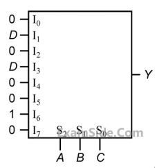
An 8-to-1 multiplexer is used to implement a logical function Y as shown in the figure. The output Y is given by
2
GATE ECE 2014 Set 4
Numerical
+2
-0
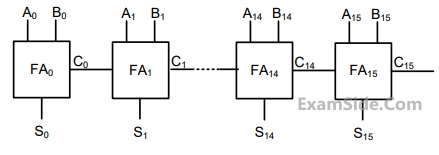
A 16-bit ripple carry adder is realized using 16 identical full adders (FA) as shown in the figure.
The carry-propagation delay of each FA is 12 ns and the sum-propagation delay of each FA is
15 ns. The worst case delay (in ns) of this 16-bit adder will be_______________.
Your input ____
3
GATE ECE 2014 Set 3
MCQ (Single Correct Answer)
+2
-0.6
If X and Y are inputs and the Difference (D = X – Y) and the Borrow (B) are the outputs, which one of the following diagrams
implements a half-subtractor?
A

B

C

D

4
GATE ECE 2014 Set 3
MCQ (Single Correct Answer)
+2
-0.6
In the circuit shown, 𝑊𝑊 and 𝑌𝑌 are MSBs of the control inputs. The output 𝐹𝐹 is given by

Questions Asked from Marks 2
GATE ECE 2024 (2) GATE ECE 2018 (1) GATE ECE 2017 Set 2 (2) GATE ECE 2016 Set 1 (2) GATE ECE 2016 Set 3 (1) GATE ECE 2015 Set 2 (1) GATE ECE 2014 Set 4 (2) GATE ECE 2014 Set 3 (2) GATE ECE 2010 (1) GATE ECE 2009 (1) GATE ECE 2008 (1) GATE ECE 2007 (1) GATE ECE 2004 (1) GATE ECE 2003 (2) GATE ECE 2001 (1) GATE ECE 1999 (1)
GATE ECE Subjects
Signals and Systems
Network Theory
Control Systems
Digital Circuits
General Aptitude
Electronic Devices and VLSI
Analog Circuits
Engineering Mathematics
Microprocessors
Communications
Electromagnetics