1
GATE EE 2016 Set 1
Numerical
+1
-0
A steady dc current of 100 A is flowing through a power module (S, D) as shown in Figure (a). The V-I characteristics of the IGBT (S) and the diode (D) are shown in Figures (b) and (c), respectively. The conduction power loss in the power module (S, D), in watts, is ________.
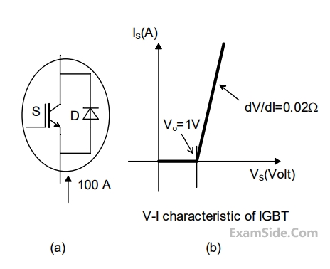
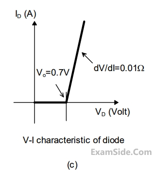
Your input ____
2
GATE EE 2014 Set 1
MCQ (Single Correct Answer)
+1
-0.3
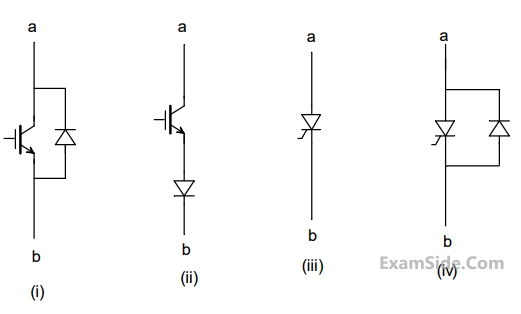
Figure shows four electronic switches $$(i), (ii), (iii)$$ and $$(iv).$$ Which of the switches can block voltages of either polarity (applied between terminals $$‘a’$$ and $$‘b’$$) when the active device is in the OFF state?
3
GATE EE 2012
MCQ (Single Correct Answer)
+1
-0.3
The typical ratio of latching current to holding current in a $$20$$ $$A$$ thyristor is
4
GATE EE 2011
MCQ (Single Correct Answer)
+1
-0.3
Circuit turn-off time of an $$SCR$$ is defined as the time
Questions Asked from Marks 1
GATE EE 2024 (1) GATE EE 2023 (1) GATE EE 2022 (1) GATE EE 2018 (1) GATE EE 2017 Set 1 (1) GATE EE 2016 Set 1 (1) GATE EE 2014 Set 1 (1) GATE EE 2012 (1) GATE EE 2011 (1) GATE EE 2010 (1) GATE EE 2009 (1) GATE EE 2005 (1) GATE EE 2004 (2) GATE EE 2003 (2) GATE EE 1998 (3) GATE EE 1997 (1) GATE EE 1996 (3) GATE EE 1995 (1) GATE EE 1994 (2) GATE EE 1993 (1)
GATE EE Subjects
Electromagnetic Fields
Signals and Systems
Engineering Mathematics
General Aptitude
Power Electronics
Power System Analysis
Analog Electronics
Control Systems
Digital Electronics
Electrical Machines
Electric Circuits
Electrical and Electronics Measurement