Signals and Systems
1
GATE ECE 2016 Set 1
Numerical
+2
-0
A sequence x$$\left[ n \right]$$ is specified as $$\left[ {\matrix{
{x\left[ n \right]} \cr
{x\left[ {n - 1} \right]} \cr
} } \right] = {\left[ {\matrix{
1 \cr
1 \cr
} \,\matrix{
1 \cr
0 \cr
} } \right]^n}\left[ {\matrix{
1 \cr
0 \cr
} } \right]$$, for n $$ \ge $$2.
The initial conditions are x$$\left[ 0 \right]$$ = 1, x$$\left[ 1 \right]$$=1 and x$$\left[ n \right]$$=0 for n< 0. The value of x$$\left[ 12 \right]$$ is _____________________.
The initial conditions are x$$\left[ 0 \right]$$ = 1, x$$\left[ 1 \right]$$=1 and x$$\left[ n \right]$$=0 for n< 0. The value of x$$\left[ 12 \right]$$ is _____________________.
Your input ____
2
GATE ECE 2016 Set 3
MCQ (Single Correct Answer)
+2
-0.6
The ROC (region of convergence) of the z-transform of a discrete-time signal is represented by the shaded
region in the z-plane. If the signal $$x\left[ n \right] = \,{\left( {2.0} \right)^{\left| n \right|}}$$ , $$ - \infty < n < + \infty $$ then the ROC of its z-transform is
represented by
A

B

C

D

3
GATE ECE 2015 Set 1
MCQ (Single Correct Answer)
+2
-0.6
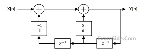
For the discrete-time system shown in the figure, the poles of the system transfer function are located at
4
GATE ECE 2015 Set 1
MCQ (Single Correct Answer)
+2
-0.6
The pole-zero diagram of a causal and stable discrete-time system is shown in the figure. The zero at the origin has
multiplicity 4. The impulse response of the system is ℎ[n]. If ℎ[0] =1, we can conclude.

GATE ECE Subjects
Signals and Systems
Network Theory
Control Systems
Digital Circuits
General Aptitude
Electronic Devices and VLSI
Analog Circuits
Engineering Mathematics
Microprocessors
Communications
Electromagnetics