Digital Electronics
Sequential Circuits
Marks 1Marks 2Marks 5
Microprocessor
Marks 1Marks 2Marks 3
Boolean Algebra
Marks 1Marks 2
Analog to Digital and Digital to Analog Converter
Marks 1Marks 2
Combinational Circuits
Marks 1Marks 2Marks 5
Minimization
Marks 2
Logic Families and Memories
Marks 1Marks 2
Logic Gates
Marks 1Marks 2
1
GATE EE 2008
MCQ (Single Correct Answer)
+2
-0.6
A $$3$$ line to $$8$$ line decoder, with active low outputs, is used to implement a $$3$$- variable Boolean function as shown in the figure: The simplified form of Boolean function $$F(X,Y,Z)$$ implemented in 'Product of Sum' form will be GATE EE 2008 Digital Electronics - Combinational Circuits Question 2 English
A
$$\left( {x + z} \right).\left( {\overline x + \overline y + \overline z } \right).\left( {y + z} \right)$$
B
$$\left( {\overline x + \overline z } \right).\left( {x + y + z} \right).\left( {\overline y + \overline z } \right)$$
C
$$\left( {\overline x + \overline y + z} \right).\left( {\overline x + y + z} \right).\left( {x + \overline y + z} \right).\left( {x + y + \overline z } \right)$$
D
$$\left( {\overline x + \overline y + \overline z } \right).\left( {\overline x + y + \overline z } \right).\left( {x + y + z} \right).\left( {x + \overline y + \overline z } \right)$$
2
GATE EE 2006
MCQ (Single Correct Answer)
+2
-0.6
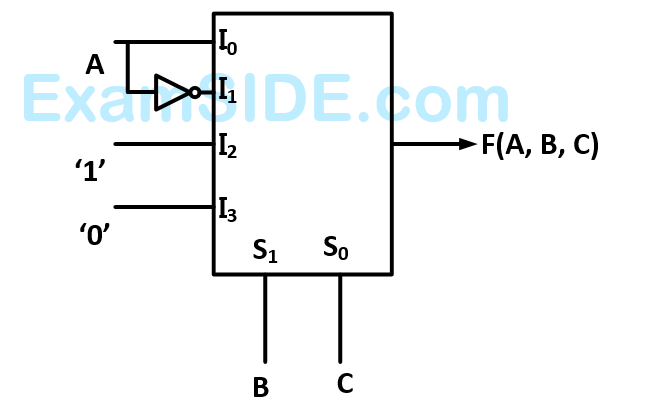
A $$4 \times 1\,\,MUX$$ is used to implement a $$3$$- input Boolean function as shown in figure. The Boolean function $$F\left( {A,\,\,B,\,\,C} \right)$$ implemented is GATE EE 2006 Digital Electronics - Combinational Circuits Question 3 English
A
$$F\left( {A,\,\,B,\,\,C} \right) = \sum \left( {1,\,\,2,\,\,4,\,\,6} \right)$$
B
$$F\left( {A,\,\,B,\,\,C} \right) = \sum \left( {1,\,\,2,\,\,6} \right)$$
C
$$F\left( {A,\,\,B,\,\,C} \right) = \sum \left( {2,\,\,4,\,\,5,\,\,6} \right)$$
D
$$F\left( {A,\,\,B,\,\,C} \right) = \sum \left( {1,\,\,5,\,\,6} \right)$$
3
GATE EE 2000
MCQ (Single Correct Answer)
+2
-0.6
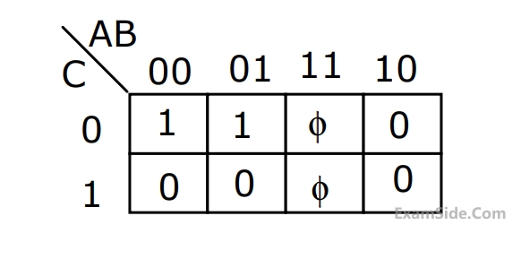
The minimal product-of-sums function described by the $$K$$-map given in Fig. GATE EE 2000 Digital Electronics - Combinational Circuits Question 9 English
A
$$\overline A \overline C $$
B
$$\overline A + \overline C $$
C
$$A+C$$
D
$$AC$$
4
GATE EE 1999
Subjective
+2
-0
The logic function $$F = AC + ABD + ACD$$ is to be realized using an $$8$$ to $$1$$ multiplexer shown in figure, using $$A, C$$ and $$D$$ as control inputs. GATE EE 1999 Digital Electronics - Combinational Circuits Question 10 English

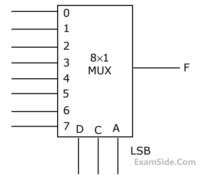
$$(a)$$ Indicate the inputs to be applied at the terminals $$0$$ to $$7.$$
$$(b)$$ Can the function be realize using a $$4$$ to $$1$$ multiplexer?
State YES or NO.

GATE EE Subjects
Electromagnetic Fields
Signals and Systems
Engineering Mathematics
General Aptitude
Power Electronics
Power System Analysis
Analog Electronics
Control Systems
Digital Electronics
Electrical Machines
Electric Circuits
Electrical and Electronics Measurement