The bus impedance matrix of a 3-bus system (in pu) is
$$ Z_{\text {bus }}=\left[\begin{array}{lll} j 0.059 & j 0.061 & j 0.038 \\ j 0.061 & j 0.093 & j 0.066 \\ j 0.038 & j 0.066 & j 0.110 \end{array}\right] $$
A symmetrical fault (through a fault impedance of $j 0.007$ p.u.) occurs at bus 2 . Neglecting pre-fault loading conditions, the voltage at bus 1 , during the fault is __________ p.u. (round off to three decimal places).
The valid positive, negative and zero sequence impedances (in p.u.), respectively, for a 220 kV, fully transported three-phase transmission line, from the given choices are
If the positive sequence impedance is (1 + 𝑗 10) $$\Omega $$, and the zero sequence is (4 + 𝑗 31) $$\Omega $$, then the imaginary part of Zm (in $$\Omega $$) is ______(up to 2 decimal places).
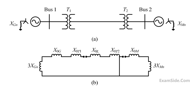
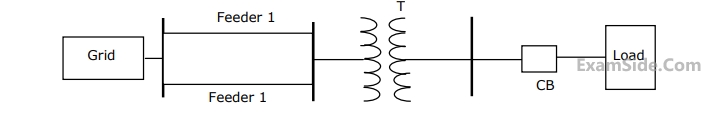
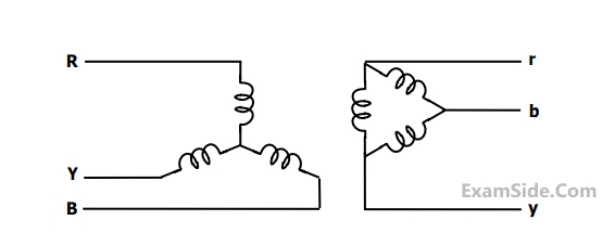
The transformers T1 and T2 are connected as
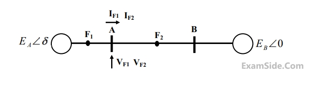
If the fault takes place at location $${F_1}$$, then the voltage and the current at bus A are $${V_F1}$$ and $${{\rm I}_{F1}}$$ respectively. If the fault takes place at location $${F_2}$$, then the voltage and the current at bus A are $${V_{F2}}$$ and $${{\rm I}_{F2}}$$ respectively.
The correct statement about voltages and currents during faults at $${F_1}$$ and $${F_2}$$ is
$${{\rm I}_{positive}} = j1.5\,pu,\,\,{{\rm I}_{negative}} = - j0.5\,\,pu,$$
$${{\rm I}_{zero}} = - j1\,\,pu.$$ The typeof fault in the system is

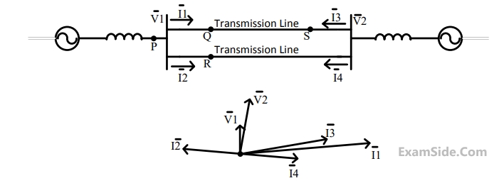
Voltage drop across the transmission line is given by the following equation:
$$$\left[ {\matrix{
{\Delta {V_a}} \cr
{\Delta {V_b}} \cr
{\Delta {V_c}} \cr
} } \right] = \left[ {\matrix{
{{Z_s}} & {{Z_m}} & {{Z_m}} \cr
{{Z_m}} & {{Z_s}} & {{Z_m}} \cr
{{Z_m}} & {{Z_m}} & {{Z_s}} \cr
} } \right]\left[ {\matrix{
{{i_a}} \cr
{{i_b}} \cr
{{i_c}} \cr
} } \right]$$$
Shunt capacitance of the line can be neglect. If the line has positive sequence impedance of $$15\,\,\Omega $$ and zero sequence in impedance of $$48\,\,\Omega ,$$ then the values of $${{Z_s}}$$ and $${{Z_m}}$$ will be
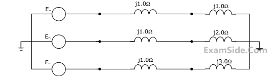
The two-bus power system shown in figure (i) has one alternator supplying a synchronous motor load through a Y-$$\Delta$$ transformer. The positive, negative and zero-sequence diagrams of the system are shown in figures (ii), (iii) and (iv), respectively. All reactances in the sequence diagrams are in p.u. For a bolted line-to-line fault (fault impedance = zero) between phases 'b' and 'c' at bus 1, neglecting all pre-fault currents, the magnitude of the fault current (from phase 'b' to 'c') in p.u. is ____________ (Round off to 2 decimal places).


Nominal system frequency $$= 50$$ $$Hz.$$ The reference voltage for phase $$'a'$$ is defined as $$\,\,V\left( t \right) = {V_m}\,\cos \left( {\omega t} \right).\,\,\,$$ A symmetrical $$3\phi $$ fault occurs at centre of the line, i.e., at point $$'F'$$ at time 'to' the $$+ve$$ sequence impedance from source $${S_1}$$ to point $$'F'$$ equals $$(0.004 + j \,\,0.04)$$ $$p.u.$$ The wave form corresponding to phase $$'a'$$ fault current from bus $$X$$ reveals that decaying $$d.c.$$ offset current is $$-ve$$ and in magnitude at its maximum initial value. Assume that the negative sequence are equal to $$+ve$$ sequence impedances and the zero sequence $$(Z)$$ are $$3$$ times $$+ve$$ sequence $$(Z).$$
The $$rms$$ value of the ac component of fault current $$\,\left( {{{\rm I}_x}} \right)$$ will be
Nominal system frequency $$= 50$$ $$Hz.$$ The reference voltage for phase $$'a'$$ is defined as $$\,\,V\left( t \right) = {V_m}\,\cos \left( {\omega t} \right).\,\,\,$$ A symmetrical $$3\phi $$ fault occurs at centre of the line, i.e., at point $$'F'$$ at time 'to' the $$+ve$$ sequence impedance from source $${S_1}$$ to point $$'F'$$ equals $$(0.004 + j \,\,0.04)$$ $$p.u.$$ The wave form corresponding to phase $$'a'$$ fault current from bus $$X$$ reveals that decaying $$d.c.$$ offset current is $$-ve$$ and in magnitude at its maximum initial value. Assume that the negative sequence are equal to $$+ve$$ sequence impedances and the zero sequence $$(Z)$$ are $$3$$ times $$+ve$$ sequence $$(Z).$$
The instant $$\,\left( {{t_0}} \right)\,\,$$ of the fault will be
Nominal system frequency $$= 50$$ $$Hz.$$ The reference voltage for phase $$'a'$$ is defined as $$\,\,V\left( t \right) = {V_m}\,\cos \left( {\omega t} \right).\,\,\,$$ A symmetrical $$3\phi $$ fault occurs at centre of the line, i.e., at point $$'F'$$ at time 'to' the $$+ve$$ sequence impedance from source $${S_1}$$ to point $$'F'$$ equals $$(0.004 + j \,\,0.04)$$ $$p.u.$$ The wave form corresponding to phase $$'a'$$ fault current from bus $$X$$ reveals that decaying $$d.c.$$ offset current is $$-ve$$ and in magnitude at its maximum initial value. Assume that the negative sequence are equal to $$+ve$$ sequence impedances and the zero sequence $$(Z)$$ are $$3$$ times $$+ve$$ sequence $$(Z).$$
Instead of the three phase fault, if a single line to ground fault occurs on phase $$' a '$$ at point $$' F '$$ with zero fault impedance, then the $$rms$$ of the ac component of fault current $$\left( {{{\rm I}_x}} \right)$$ for phase $$'a'$$ will be
$$\left[ {\matrix{ {{f_a}} \cr {{f_b}} \cr {{f_c}} \cr } } \right] = k\left[ {\matrix{ 1 & 1 & 1 \cr {{\alpha ^2}} & \alpha & 1 \cr \alpha & {{\alpha ^2}} & 1 \cr } } \right]\left[ {\matrix{ {{f_p}} \cr {{f_n}} \cr {{f_o}} \cr } } \right]$$ where $$\,\alpha = {e^{j{{2\pi } \over 3}}}\,\,$$ and $$k$$ is a constant
Now, if it is given that:
$$\left[ {\matrix{ {{V_p}} \cr {{V_n}} \cr {{V_o}} \cr } } \right] = k\left[ {\matrix{ {0.5} & 0 & 0 \cr 0 & {0.5} & 0 \cr 0 & 0 & {2.0} \cr } } \right]\left[ {\matrix{ {{i_p}} \cr {{I_n}} \cr {{i_o}} \cr } } \right]\,\,$$ and $$\left[ {\matrix{ {{V_a}} \cr {{V_b}} \cr {{V_c}} \cr } } \right] = z\left[ {\matrix{ {{i_a}} \cr {{I_b}} \cr {{i_c}} \cr } } \right]\,\,$$ then,
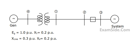
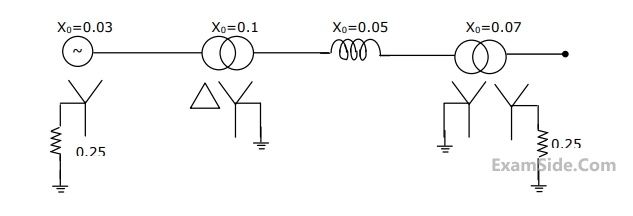
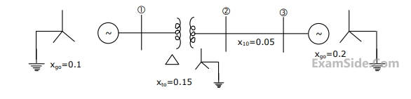
The positive sequence driving point reactance at the bus is
The zero sequence driving point reactance at the bus is
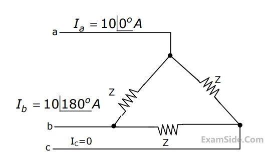
$${E_a} = 10\angle {0^ \circ }V,\,\,\,{E_b} = 10\angle - {90^ \circ }V,\,\,{E_c} = 10\angle {120^ \circ }\,\,V.\,\,\,\,$$ The positive sequence component of the load current is
$$1.0$$ p.u. and $${Z_1} = {Z_2} = j0.1\,\,$$ p.u.,
$$\,{Z_0} = j0.05\,\,\,\,\,$$ p.u., for the alternator, then the required inductive reacttance for neutral grounding is
(a) Draw the positive, negative, and zero sequence networks for the fault given.
(b) Draw the interconnection of the sequence networks for the fault analysis.
(c) Determine the fault current.