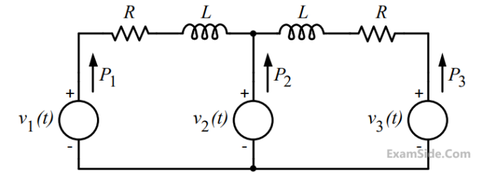
A 50 Hz, 275 kV line of length 400 km has the following parameters:
Resistance, R = 0.035 $$\Omega$$/km;
Inductance, L = 1 mH/km;
Capacitance, C = 0.01 $$\mu$$F/km;
The line is represented by the nominal-$$\pi$$ model. With the magnitudes of the sending end and the receiving end voltages of the line (denoted by $$V_S$$ and $$V_R$$, respectively) maintained at 275 kV, the phase angle difference ($$\theta$$) between $$V_S$$ and $$V_R$$ required for maximum possible active power to be delivered to the receiving end, in degree is ___________ (Round off to 2 decimal places).
The geometric mean radius of a conductor, having four equal strands with each strand of radius r, as shown in the figure below, is

$${v_1}\left( t \right) = 100\cos \left( {\omega t} \right)$$
$${v_2}\left( t \right) = 100\cos \left( {\omega t + {\pi \over {18}}} \right)$$
and $${v_3}\left( t \right) = 100\cos \left( {\omega t + {\pi \over {36}}} \right)$$.
The circuit is in sinusoidal steady state, and R << $${\omega L}$$. P1, P2 and P3 are the average power outputs. Which one of the following statements is true?


Impedance $$Z = 100\angle {80^ \circ }$$ and reactance $$\,X = 3300\Omega .$$ The magnitude of the characteristic impedance of the transmission line, in $$\Omega ,$$ is ________. (Give the answer up to one decimal place.)
 The total instantaneous power flowing form the source to the load is


The value of $${V_1}$$ in $$p.u$$ and $${\delta _2}$$ respectively are

The contributions of $${S_1}$$ and $${S_2}$$ in $$100$$ $$A$$ current supplied at location $$P$$ respectively, are


List-$${\rm I}$$
$$A.$$ improve power factor
$$B.$$ reduce the current ripples
$$C.$$ increase the power flow in line
$$D$$ reduce the Ferranti effect
List-$${\rm II}$$
$$1.$$ shunt reactor
$$2.$$ shunt capacitor
$$3.$$ series capacitor
$$4.$$ series reactor

Distribution Company's policy requires radial system operation with minimum loss. This can be achieved by opening of the branch
$$A = D = 0.94\,\angle \,10,\,\,\,B = 130\,\angle \,730,\,\,\,C = 0.001\,\angle \,900.\,\,$$ If the sending end voltage of the line for a given load delivered at nominal voltage is $$240$$ $$kV$$, the % voltage regulation of the line is
$$B = 33.5 + j138 = 142.0\angle {76.4^ \circ }\,\Omega $$
$$\,C = \left( { - 5.18 + j914} \right) \times \,{10^{ - 6}}\,\Omega $$
If the load at the receiving end is $$50$$ MW at $$220$$ $$kV$$ with a power factor of 0.9 lagging, then magnitude of line to line sending end voltage should be


(a) Calculate the voltage on the line-end unit.
(b) Calculate the value of capacitance $${C_x}$$ required.
Characteristic impedance $${Z_c} = 400\Omega ,\,\,$$, propagation constant $$\,\beta = 1.2 \times {10^{ - 3}}\,\,rad/km,\,\,$$ and length $$\,l = 100\,km.\,\,$$ The equation relating sending and receiving end questions is $${V_s} = {V_r}\,\cosh \,\,\left( {\beta l} \right) + j\,Z{}_c\,\,\sinh \left( {\beta l} \right){{\rm I}_R}$$ Complete the maximum power that can be transferred to the UPF load at the receiving end if $$\left| {{V_s}} \right| = 230\,\,kV.\,\,$$

(a) Calculate the value of this voltage surge when it first reaches C.
(b) Calculate the value of the reflected component of this surge when the first reflection reaches A.
(c) Calculate the surge current in the cable BC.
$$x=0.05$$ $$ohms/km,$$ line charging susceptance $$y=3.0$$ micro-Siemens/k.
(a) Calculate the receiving end voltage on open circuit using justifiable assumptions.
(b) What load at the receiving end will result in a flat voltage profile on the line?
(c) If the flat voltage profile is to be achieved at $$1.2$$ times the loading in (b), what will be the nature and quantum of uniformly distributed compensation required?
(a) Draw the nominal π-equivalent circuit and indicate the value of each parameter.
(b) Calculate the receiving end voltage if the sending end voltage is 66 kV.
Conductor diameter: 1.5 cm, length: 4 km. Internal diameter of the sheath : 3 cm
Resistivity of insulation : 1.3 $$ \times $$ 1012 $$\Omega $$-m. Relative permittivity of insulation : 3.5 Calculate
(a) the insulation resistance
(b) the capacitance and
(c) the maximum electric stress in the insulation