Power System Analysis
High Voltage Dc Transmission
Marks 11
GATE EE 2024
MCQ (Single Correct Answer)
+2
-1.33
For the three-bus lossless power network shown in the figure, the voltage magnitudes at all the buses are equal to 1 per unit (pu), and the differences of the voltage phase angles are very small. The line reactances are marked in the figure, where $\alpha$, $\beta$, $\gamma$, and $x$ are strictly positive. The bus injections $P_1$ and $P_2$ are in pu. If $P_1 = mP_2$, where $m > 0$, and the real power flow from bus 1 to bus 2 is 0 pu, then which one of the following options is correct?

2
GATE EE 2018
MCQ (Single Correct Answer)
+2
-0.67
The per-unit power output of a salient-pole generator which is connected to an infinite bus,
is given by the expression, P = 1.4 sin $$\delta $$ + 0.15 sin 2$$\delta $$, where $$\delta $$ is the load angle. Newton-Raphson method is used to calculate the value of $$\delta $$ for P = 0.8 pu. If the initial guess is
$$30^\circ $$, then its value (in degree) at the end of the first iteration is
3
GATE EE 2017 Set 1
MCQ (Single Correct Answer)
+2
-0.6
The bus admittance matrix for a power system network is
$$$\left[ {\matrix{
{ - j39.9} & {j20} & {j20} \cr
{j20} & { - j39.9} & {j20} \cr
{j20} & {j20} & { - j39.9} \cr
} } \right]\,pu.$$$
There is a transmission line connected between buses $$1$$ and $$3,$$ which is represented by the circuit shown in figure.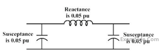
There is a transmission line connected between buses $$1$$ and $$3,$$ which is represented by the circuit shown in figure.
If this transmission line is removed from service what is the modified bus admittance matrix?
4
GATE EE 2015 Set 1
MCQ (Single Correct Answer)
+2
-0.6
Determine the correctness or otherwise of the following Assertion (a) and the Reason (R).
Assertion (A): Fast decoupled load flow method gives approximate load flow solution because it uses several assumptions.
Reason (R): Accuracy depends on the power mismatch vector tolerance.
Assertion (A): Fast decoupled load flow method gives approximate load flow solution because it uses several assumptions.
Reason (R): Accuracy depends on the power mismatch vector tolerance.
GATE EE Subjects
Electromagnetic Fields
Signals and Systems
Engineering Mathematics
General Aptitude
Power Electronics
Power System Analysis
Analog Electronics
Control Systems
Digital Electronics
Electrical Machines
Electric Circuits
Electrical and Electronics Measurement