Logic Families and Memories
Practice QuestionsMarks 1
1
If $${X_1}$$ and $${X_2}$$ are the inputs to the circuit shown in the figure, the output $$Q$$ is

GATE EE 2005
2
In standard $$TTL$$ gates, the totem pole output stage is primarily used to
GATE EE 1998
3
The open collector outputs of two$$2$$-inputs $$NAND$$ gates are connected to a common pull up resistor. If the input to the gates are $$P,Q$$ and $$R,S$$ respectively, the output is equal to
GATE EE 1998
Marks 2
1
The $$TTL$$ circuit shown in the figure is fed with the waveform $$X$$ (also shown). All gates have equal propagation delay of $$10$$ $$ns.$$ The output $$Y$$ of the circuit is


GATE EE 2010
2
A TTL NOT gate circuit is shown in figure. Assuming $${V_{BE}} = 0.7\,v$$ of both the transistors, if $${V_i} = 3.0\,V,$$ then the states of the two transistors will be
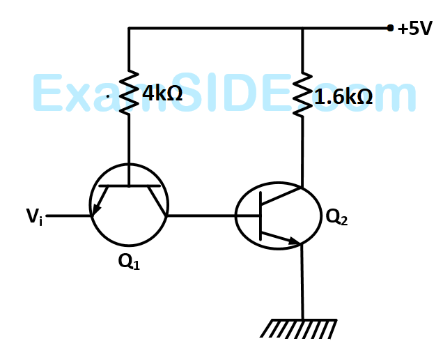
GATE EE 2006