Digital Circuits
1
GATE ECE 2013
MCQ (Single Correct Answer)
+2
-0.6
In the circuit shown below, Q1 has negligible collector-to-emitter saturation voltage and the diode
drops negligible voltage across it under forward bias. If VCC is +5 V, X and Y are digital signals
with 0 V as logic 0 and VCC as logic 1, then the Boolean expression for Z is

2
GATE ECE 2008
MCQ (Single Correct Answer)
+2
-0.6
The logic function implemented by the following circuit at the terminal OUT is

3
GATE ECE 2007
MCQ (Single Correct Answer)
+2
-0.6
The circuit diagram of a standard TTL NOT gate is shown in the figure. When $${V_i}$$= 2.5V, the modes of operation of the transistors will be:

4
GATE ECE 2003
MCQ (Single Correct Answer)
+2
-0.6
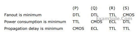
The DTL, TTL, ECL and CMOS families of digital ICs are compared in the following 4 columns
Questions Asked from Marks 2
GATE ECE Subjects
Signals and Systems
Network Theory
Control Systems
Digital Circuits
General Aptitude
Electronic Devices and VLSI
Analog Circuits
Engineering Mathematics
Microprocessors
Communications
Electromagnetics