Digital Circuits
1
GATE ECE 2022
MCQ (More than One Correct Answer)
+1
-0
Select the correct statement(s) regarding CMOS implementation of NOT gates.
2
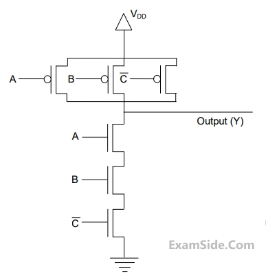
GATE ECE 2014 Set 4
MCQ (Single Correct Answer)
+1
-0.3
The output (Y) of the circuit shown in the figure is
3
GATE ECE 2009
MCQ (Single Correct Answer)
+1
-0.3
The full forms of the abbreviations TTL and COMS in reference to logic families are
4
GATE ECE 2005
MCQ (Single Correct Answer)
+1
-0.3
Both transistors T1 and T2 in figure have a threshold voltage of 1 Volt. The device parameters $${K_1}$$ and $${K_2}$$ of $${T_1}$$ and $${T_2}$$ are, respectively, 36 µA/ $${V^2}$$ and
and 9$$9\,A/{V^2}$$. The output voltage $${V_0}$$ IS

GATE ECE Subjects
Signals and Systems
Network Theory
Control Systems
Digital Circuits
General Aptitude
Electronic Devices and VLSI
Analog Circuits
Engineering Mathematics
Microprocessors
Communications
Electromagnetics