Digital Circuits
1
GATE ECE 2002
Subjective
+5
-0
The inputs to a digital circuit shown in Figure 9(a) are the external signals A, B and C.
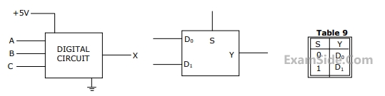 ( $$\overline A \,\overline B \,and\,\overline {C\,} $$ and are not available). The +5V power supply (logic 1) and the ground
(logic 0) are also available. The output of the circuit is X = $$\overline A \,B + \,\overline A \,\overline B \,\,\overline {C\,} $$
( $$\overline A \,\overline B \,and\,\overline {C\,} $$ and are not available). The +5V power supply (logic 1) and the ground
(logic 0) are also available. The output of the circuit is X = $$\overline A \,B + \,\overline A \,\overline B \,\,\overline {C\,} $$
(a) Write down the output function in its canonical SOP and POS forms.
(b) Implement the circuit using only two 2:1 multiplexers shown in the Figure where S is the data-select line, $${D_0}\,$$ and $${D_1}\,$$ are the input data lines and Y is the output lines. The function table for the multiplexer is given in table
Questions Asked from Marks 5
GATE ECE Subjects
Signals and Systems
Network Theory
Control Systems
Digital Circuits
General Aptitude
Electronic Devices and VLSI
Analog Circuits
Engineering Mathematics
Microprocessors
Communications
Electromagnetics