In the circuit shown, the n : 1 step-down transformer and the diodes are ideal. The diodes have no voltage drop in forward biased condition. If the input voltage (in Volts) is $V_s(t) = 10 \sin\omega t$ and the average value of load voltage $V_L(t)$ (in Volts) is $\frac{2.5}{\pi}$, the value of n is _____.

As shown in the circuit, the initial voltage across the capacitor is 10 V, with the switch being open. The switch is then closed at $t = 0$. The total energy dissipated in the ideal Zener diode $(V_Z = 5 ext{ V})$ after the switch is closed (in mJ, rounded off to three decimal places) is _________.


 The magnitude of the current i2 (in mA) is equal to __________.


(1) less expensive transformer
(2) smaller size transformer, and
(3) suitability for higher voltage application.
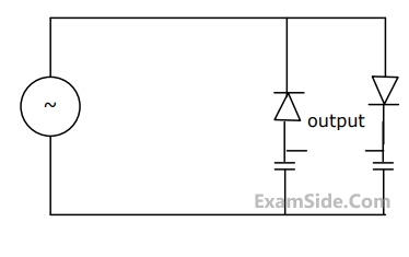
Of these,All the diodes in the circuit given below are ideal.
Which of the following plots is/are correct when $V_I$ (in Volts) is swept from $-M$ to $M$ ?

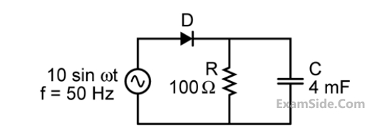
The diode in the circuit shown below is ideal. The input voltage (in Volts) is given by $V_1=10 \sin 100 \pi t$, where time $t$ is in seconds.
The time duration (in ms, rounded off to two decimal places) for which the diode is forward biased during one period of the input is ________.

In the circuit shown below, D$$_1$$ and D$$_2$$ are silicon diodes with cut-in voltage of 0.7 V. $$\mathrm{V_{IN}}$$ and $$\mathrm{V_{OUT}}$$ are input and output voltages in volts. The transfer characteristic is

A circuit and the characteristics of the diode (D) in it are shown. The ratio of the minimum to the maximum small signal voltage gain $${{\partial {V_{out}}} \over {\partial {V_{in}}}}$$ is __________ (rounded off to two decimal places).


The value of the ripple u (in volts) is ______________.

 The ac output voltage vac is
The bias current IDC through the diodes is
The ac output voltage vac is
The bias current IDC through the diodes is